
이번 posting에서는 RIoT board(NXP/freescale i.MX6 Solo processor 탑재)를 사용하여, yocto project 개발 환경에서 최신 linux device driver를 작성하는 방법을 소개해 보도록 하겠다.
RIoT Board(ARM Cortex-A9) + device tree + platform driver + yocto project

<목차>
1. 머릿말
2. RIoT board 개발 환경 소개(Yocto project 기반)
- Yocto project
- Yocto 상에서 kernel & module build 방법
3. Linux device driver model with device tree
- Bus driver/bus controller driver/device driver model
- Device tree와 platform driver 개념
- Machine 초기화 과정 분석
4. Platform driver 예제 소개
- GPIO LED control
- Ioremap
- Pin muxing(Pinctrl)
- Sysfs
- User space IO driver
5. Interrupt platform driver 예제 소개
- Device tree & interrupt handling
- Bottom halves
6. Input subsystem driver 예제 소개
- I2C accelerometer, magnetometer, gyroscope and input subsystem
7. Industrial I/O(IIO) subsystem driver 예제 소개
- DAC, ADC
- I2C driver
- SPI driver
8. 맺음말
- Embedded linux kernel/driver programming에 관한 고찰
----------------------------------------------------------------------------------------------------------------------
1. 머릿말
본 저자는 이미 여러 차례에 걸쳐 linux kernel & device driver programming에 관한 내용을 소개한 바 있다. 하지만 아직도 뭔가 2% 부족한 느낌은 왜일까 ? 쭉~ 따라가면서 해보면 전체적으로 공부가 되는 효과적인 방법은 없을까 ?
이번 글은 이러한 갈증을 해소(?)하기 위한 목적에서 작성하기 시작하였다. 내용 중 일부는 이전 posting에서 소개했던 것들과 겹치는 부분도 있겠으나, 최신 linux kernel 4.x + platform driver with device tree + yocto project를 다룬다는 점에서 그 의미를 부여하고 싶다. Linux kernel & device driver programming에 목말라(?) 있는 분들에게 조금이라도 도움이 되었으면 하는 바램이다. 오늘은 왠지 시작부터 너무 거창하다... 😎
<linux kernel & device driver programming 관련 이전 글>
1) beaglebone black을 이용한 device driver programming(device tree, uart, i2c, spi, ...)
=> http://slowbootkernelhacks.blogspot.kr/2014/03/beaglebone-linux-kernel310x-programming.html
2) linux 4.x 상에서 유용하게 사용할 kernel programming 기법 검토 1/2(non-device tree 기반, github에 source code 제공)
=> http://slowbootkernelhacks.blogspot.kr/2017/03/linux-kernel-programming-guide.html
=> http://slowbootkernelhacks.blogspot.kr/2017/03/efficient-linux-kernel-4x-programming.html
3) 몇가지 sensor 관련 driver programming(device tree 기반)
=> http://slowbootkernelhacks.blogspot.kr/2017/04/linux-device-driver-programming-using.html
4) atmel sama5d3 xplained board 상에서 lcd 연결하기(device tree 기반)
=> http://slowbootkernelhacks.blogspot.kr/2016/12/how-to-connect-tft-lcd-to-atmel-sama5d3.html
<이번 posting에서 다루고자 하는 주제>
1) device tree & platform driver가 연결된 예제
2) pinmux driver 예제
3) device tree 기반의 gpio interrupt 예제
4) virtual memory 개념(ioremap, mmap)
5) input sub system, iio subsystem 예제(i2c, spi driver)
6) user space driver(uio) 예제
7) yocto project에 kernel module 추가하기 및 yocto project 관련 추가 Tips
앞선 posting의 내용과 이번 posting의 내용을 읽어 본 후, 그래도 부족하다거나 추가로 검토가 필요하다고 판단이 되는 부분이 있다면, 의견을 남겨 주기 바란다.
RIoT board 및 Yocto project와 관련해서는 이미 이전 posting을 통해 개략적인 내용을 소개한 바 있다. 따라서 자세한 사항은 아래 link를 먼저 참조해 주기 바란다.
<RIoT board 관련>
<Yocto project 관련>
2.1 Yocto 개발환경 준비
$ cd ~/IoT/RIoTBoard/yocto/fsl-community-bsp
=> yocto 작업 디렉토리로 이동한다.
$ MACHINE=imx6dl-riotboard source setup-environment imx6dl-riotboard
=> yocto build를 위한 환경 설정을 진행한다. 현재 디렉토리를 imx6dl-riotboard 아래로 자동 이동시킨다.
=> setup-environment 파일은 oe-init-build-env 실행을 위한 wrapper shell script에 불과함.
Welcome to Freescale Community BSP
The Yocto Project has extensive documentation about OE including a
reference manual which can be found at:
http://yoctoproject.org/documentation
For more information about OpenEmbedded see their website:
http://www.openembedded.org/
You can now run 'bitbake <target>'
Common targets are:
core-image-minimal
meta-toolchain
meta-toolchain-sdk
adt-installer
meta-ide-support
Your configuration files at imx6dl-riotboard have not been touched.
$ bitbake core-image-minimal
=> core-image-minimal.bb 레시피에 맞는 image를 생성한다.
=> 이 명령을 수행하기에 앞서 필요한 절차(config file 수정 등)는 생략하였음.
=> 3 ~ 4 시간의 build 작업 후, tmp/deploy/images/imx6dl-riotboard 디렉토리에 아래에 build 결과물이 만들어지게 됨.
$ bitbake -c populate_sdk core-image-minimal
=> SDK(toolchain 포함)를 생성한다.
=> 참고: toolchain만 build하고자 한다면, bitbake meta-toolchain 명령을 실행하면 된다.
$ ./tmp/deploy/sdk/poky-glibc-x86_64-core-image-minimal-armv7a-neon-toolchain-2.1.2.sh
=> SDK를 설치한다.
=> 편의상 /opt/poky/2.1.2 아래에 설치하기로 함.
$ source /opt/poky/2.1.2/environment-setup-armv7a-neon-poky-linux-gnueabi
=> toolchain 환경 설정 내용을 적용한다(compile 진행 전에 실행해 주자).
=> .bashrc에 위의 내용을 추가해 주거나, terminal을 띄울 때마다 위의 내용을 실행해 준다.
2.2 kernel build 방법 소개
Driver programming을 하다 보면, kernel config를 조정하거나, kernel을 재 build해야 하는 상황이 자주 발생하게 된다. 따라서 이번절에서는 yocto 환경에서 kernel을 build하기 위한 절차를 소개해 보고자 한다. 아래 link의 1절에도 유사한 내용이 상세히 설명되어 있으니, 참조해 보기 바란다.
<kernel 단독 build 절차>
$ bitbake -c cleanall virtual/kernel
=> build 디렉토리, shared state cache, download한 package source 등을 모두 지운다.
=> 단, 이 과정은 꼭 필요한 경우를 제외하고는 수행할 필요 없음.
$ bitbake -c configure virtual/kernel
=> fetch, unpack, configure 등의 task를 수행한다.
=> defconfig를 .config로 복사하여 build 디렉토리에 위치시키고, oldconfig를 call한다.
$ bitbake -c menuconfig virtual/kernel
=> make menuconfig 단계에 해당한다.
=> 다른 terminal 창에 menuconfig 화면이 뜬다. 여기서 kernel config를 조정하자.
$ bitbake -c savedefconfig virtual/kernel
=> menuconfig에서 변경한 내용(.config)을 같은 디렉토리(build) 아래에 defconfig 파일로 저장(불필요한 내용 제거)한다.
=> menuconfig에서 변경한 내용(.config)을 같은 디렉토리(build) 아래에 defconfig 파일로 저장(불필요한 내용 제거)한다.
=> 중요: 변경 사항이 clean build 이후에도 남아 있도록 하려면, defconfig 파일을 적절한 recipe 디렉토리(예:sources/meta-fsl-arm/recipes-kernel/linux/linux-fslc)에 복사해 주어야 한다.
--------------------------------------------------------------------------------------------------------------------
<savedefconfig 명령 수행 후 상세 절차 예>
$ bitbake -e virtual/kernel | grep ^WORKDIR=
WORKDIR="/home/chyi/IoT/RIoTBoard/yocto/fsl-community-bsp/imx6dl-riotboard/tmp/work/imx6dl_riotboard-poky-linux-gnueabi/linux-fslc/4.4+gitAUTOINC+928f8d55df-r0"
=> kernel working directory를 찾는다.
$ cd /home/chyi/IoT/RIoTBoard/yocto/fsl-community-bsp/imx6dl-riotboard/tmp/work/imx6dl_riotboard-poky-linux-gnueabi/linux-fslc/4.4+gitAUTOINC+928f8d55df-r0
$ cd build
=> kernel working directory로 이동한다.
$ cp ./defconfig ~/IoT/RIoTBoard/yocto/fsl-community-bsp/sources/meta-fsl-arm/recipes-kernel/linux/linux-fslc
=> defconfig 파일을 kernel recipe 디렉토리로 복사한다.
=> 주의: meta-fsl-arm/recipes-kernel/linux/linux-fslc가 RIoT board를 위한 defconfig를 담고 있는지를 사전에 알아낼 수 있어야 함.
=> defconfig 파일을 kernel recipe 디렉토리로 복사한다.
=> 주의: meta-fsl-arm/recipes-kernel/linux/linux-fslc가 RIoT board를 위한 defconfig를 담고 있는지를 사전에 알아낼 수 있어야 함.
--------------------------------------------------------------------------------------------------------------------
$ bitbake -c devshell virtual/kernel
=> 별도의 terminal을 띄우고 kernel source directory로 이동한다(kernel build 환경이 자동으로 설정됨)
=> 여기서 code 수정 & build 작업 등을 진행하고, git에 반영할 내용이 있다면 반영하도록 한다.
-------------------------------------------------------------------------------
$ make zImage$ make modules
$ make dtbs
=> bitbake 명령을 사용할 필요 없이, make로 직접 build가 가능하다. build 중간 결과물은 build 디렉토리에 생성됨.
...
$ git add --all .
$ git commit -s -m "your commit messages"
-------------------------------------------------------------------------------
$ bitbake -C compile virtual/kernel
=> compile 및 그 이후의 모든 task(image 생성까지)를 진행한다.
=> 주의: 이전 terminal로 돌아와 위 명령을 수행해 주어야 한다.
=> 위 명령은 아래의 두 명령으로도 대체 가능하다.
-------------------------------------------------------------------------------
$ bitbake -f -c compile virtual/kernel
$ bitbake -c deploy virtual/kernel
-------------------------------------------------------------------------------
=> 위 명령은 아래의 두 명령으로도 대체 가능하다.
-------------------------------------------------------------------------------
$ bitbake -f -c compile virtual/kernel
$ bitbake -c deploy virtual/kernel
-------------------------------------------------------------------------------
$ cd tmp/deploy/images/imx6dl-riotboard
=> build 결과물이 위치한 디렉토리로 이동한다.
$ sudo cp ./zImage /tftpboot
=> (NFS booting을 위해) kernel image를 tftp 서버 디렉토리로 복사한다.
$ sudo cp ./zImage-imx6dl-riotboard.dtb /tftpboot/imx6solo_RIoTboard.dtb
=> (NFS booting을 위해) dtb file을 복사한다.
참고 사항: 보통 kernel이나 bootloader의 경우는 별도로 분리(yocto directory와 source 위치를 별도로 분리, 단, yocto 전체 build 과정에는 포함시킴)하여 작업하는 경향이 있으므로, 위와 같이 복잡한 방식을 반드시 사용해야 하는 것이 아니다 😗.
여기서 잠깐 ! RIoT board kernel metadata 구조 분석
------------------------------------------------------------------------------------------------------------------------------------
RIoT board의 kernel 구성과 관련한 meta data(configuration, recipe, class 등)가 어떤 식으로 구성되어 있는지 확인할 필요가 있다. 이는 kernel(or bootloader, device tree)을 어떤 형태(or version)로 download 받아 patch를 적용하고, 어떤 형태로 build하는 지 등을 확인하기 위해 필요한 절차라고 볼 수 있다.
a) machine conf 관계
$ vi sources/meta-fsl-arm-extra/conf/machine/imx6dl-riotboard.conf
-------------------------------------------------------------------------
#@TYPE: Machine
#@NAME: RIoTboard
#@SOC: i.MX6S
#@DESCRIPTION: Machine configuration for i.MX6S RIoTboard.
#@MAINTAINER: Nikolay Dimitrov <picmaster@mail.bg>
include conf/machine/include/imx-base.inc ...................... 아래 [A] 참조
include conf/machine/include/tune-cortexa9.inc
UBOOT_MACHINE = "riotboard_defconfig"
PREFERRED_PROVIDER_virtual/kernel ?= "linux-fslc"
KERNEL_DEVICETREE = "imx6dl-riotboard.dtb"
SERIAL_CONSOLE = "115200 ttymxc1"
-------------------------------------------------------------------------
$ vi sources/meta-fsl-arm/conf/machine/include/imx-base.inc ............. [A]
-------------------------------------------------------------------------
# Provides the i.MX common settings
include conf/machine/include/fsl-default-settings.inc
include conf/machine/include/fsl-default-versions.inc
include conf/machine/include/soc-family.inc
# Set specific make target and binary suffix
PREFERRED_PROVIDER_u-boot ??= "u-boot-fslc"
PREFERRED_PROVIDER_virtual/bootloader ??= "u-boot-fslc"
PREFERRED_PROVIDER_u-boot-mxsboot-native ??= "u-boot-fslc-mxsboot-native"
UBOOT_MAKE_TARGET ?= "u-boot.imx"
UBOOT_MAKE_TARGET_mxs ?= "u-boot.sb"
UBOOT_SUFFIX ?= "imx"
UBOOT_SUFFIX_mxs ?= "sb"
UBOOT_ENTRYPOINT_mxs = "0x40008000"
UBOOT_ENTRYPOINT_mx51 = "0x90008000"
UBOOT_ENTRYPOINT_mx53 = "0x70008000"
UBOOT_ENTRYPOINT_mx6 = "0x10008000"
UBOOT_ENTRYPOINT_mx6sl = "0x80008000"
UBOOT_ENTRYPOINT_mx6sx = "0x80008000"
UBOOT_ENTRYPOINT_mx6ul = "0x10008000"
UBOOT_ENTRYPOINT_mx7 = "0x80008000"
UBOOT_ENTRYPOINT_vf = "0x80008000"
PREFERRED_PROVIDER_virtual/xserver = "xserver-xorg"
XSERVER_DRIVER = "xf86-video-fbdev"
XSERVER_DRIVER_mx6 = "xf86-video-imxfb-vivante"
XSERVER_DRIVER_vf = "xf86-video-modesetting"
XSERVER = "xserver-xorg \
xf86-input-evdev \
${XSERVER_DRIVER}"
# Ship kernel modules
MACHINE_EXTRA_RRECOMMENDS = "kernel-modules"
... [생략]...
# Handle default kernel
IMX_DEFAULT_KERNEL = "linux-imx"
IMX_DEFAULT_KERNEL_mxs = "linux-fslc"
IMX_DEFAULT_KERNEL_mx5 = "linux-fslc"
IMX_DEFAULT_KERNEL_mx6 = "linux-fslc-imx"
IMX_DEFAULT_KERNEL_mx7 = "linux-fslc-imx"
IMX_DEFAULT_KERNEL_mx6ul = "linux-fslc-imx"
PREFERRED_PROVIDER_virtual/kernel ??= "${IMX_DEFAULT_KERNEL}"
SOC_DEFAULT_IMAGE_FSTYPES = "sdcard.gz"
SOC_DEFAULT_IMAGE_FSTYPES_mxs = "uboot.mxsboot-sdcard sdcard.gz"
SDCARD_ROOTFS ?= "${DEPLOY_DIR_IMAGE}/${IMAGE_NAME}.rootfs.ext4"
IMAGE_FSTYPES ?= "${SOC_DEFAULT_IMAGE_FSTYPES}"
SERIAL_CONSOLE = "115200 ttymxc0"
SERIAL_CONSOLE_mxs = "115200 ttyAMA0"
KERNEL_IMAGETYPE = "zImage"
MACHINE_FEATURES = "usbgadget usbhost vfat alsa touchscreen"
# Add the ability to specify _imx machines
MACHINEOVERRIDES =. "imx:"
-------------------------------------------------------------------------
b) kernel recipe 흐름
-------------------------------------------------------------------------
<meta-fsl-arm/recipes-kernel/linux/linux-imx.inc>
# Copyright (C) 2012, 2015 O.S. Systems Software LTDA.
# Released under the MIT license (see COPYING.MIT for the terms)
LICENSE = "GPLv2"
LIC_FILES_CHKSUM = "file://COPYING;md5=d7810fab7487fb0aad327b76f1be7cd7"
inherit kernel fsl-kernel-localversion fsl-vivante-kernel-driver-handler
# Put a local version until we have a true SRCREV to point to
LOCALVERSION ?= ""
SCMVERSION ?= "y"
SRCBRANCH ?= ""
SRC_URI = "git://git.freescale.com/imx/linux-2.6-imx.git;branch=${SRCBRANCH} \
file://defconfig \
"
S = "${WORKDIR}/git"
# We need to pass it as param since kernel might support more then one
# machine, with different entry points
KERNEL_EXTRA_ARGS += "LOADADDR=${UBOOT_ENTRYPOINT}"
-------------------------------------------------------------------------
^
||
-------------------------------------------------------------------------
<meta-fsl-arm/recipes-kernel/linux/linux-fslc.inc>
# Copyright (C) 2012-2015 O.S. Systems Software LTDA.
# Released under the MIT license (see COPYING.MIT for the terms)
require recipes-kernel/linux/linux-imx.inc
require recipes-kernel/linux/linux-dtb.inc
DEPENDS += "lzop-native bc-native"
SRC_URI = "git://github.com/Freescale/linux-fslc.git;branch=${SRCBRANCH} \
file://defconfig"
LOCALVERSION = "-fslc"
-------------------------------------------------------------------------
^
||
-------------------------------------------------------------------------
<recipes-kernel/linux/linux-fslc_4.4.bb>
# Copyright (C) 2012-2015 O.S. Systems Software LTDA.
# Released under the MIT license (see COPYING.MIT for the terms)
SUMMARY = "FSL Community BSP Linux mainline based kernel with backported features and fixes"
DESCRIPTION = "Linux kernel based on mainline kernel used by FSL Community BSP in order to \
provide support for some backported features and fixes, or because it was applied in linux-next \
and takes some time to become part of a stable version, or because it is not applicable for \
upstreaming."
include linux-fslc.inc
PV = "4.4+git${SRCPV}"
SRCBRANCH = "4.4.x"
SRCREV = "928f8d55df92dce453ac6514d26abb1d66f0e123"
COMPATIBLE_MACHINE = "(mxs|mx5|mx6|vf)"
-------------------------------------------------------------------------
------------------------------------------------------------------------------------------------------------------------------------
2.3 kernel module build 방법 소개
<kernel module build하기>
먼저 아래와 같이 hello_world.c 파일과 Makefile을 만들었다고 가정하자.
----------------------------------------------------------------------------------------------------------------------------------
<kernel module Makefile 예>
obj-m += hello_world.o
export KERNEL_SRC=/home/chyi/IoT/RIoTBoard/yocto/fsl-community-bsp/imx6dl-riotboard/tmp/work/imx6dl_riotboard-poky-linux-gnueabi/linux-fslc/4.4+gitAUTOINC+928f8d55df-r0/build
export ARCH=arm
allofit: modules
modules:
@$(MAKE) -C $(KERNEL_SRC) M=$(PWD) modules
modules_install:
@$(MAKE) -C $(KERNEL_SRC) M=$(PWD) modules_install
kernel_clean:
@$(MAKE) -C $(KERNEL_SRC) M=$(PWD) clean
clean: kernel_clean
rm -rf Module.symvers modules.order
----------------------------------------------------------------------------------------------------------------------------------
/* hello_world.c */
#include <linux/module.h>
static int __init hello_init(void)
{
pr_info("Hello world !\n");
return 0;
}
static void __exit hello_exit(void)
{
pr_info("Good bye !\n");
}
module_init(hello_init);
module_exit(hello_exit);
MODULE_LICENSE("GPL v2");
----------------------------------------------------------------------------------------------------------------------------------
$ bitbake -e virtual/kernel | grep ^WORKDIR=
=> kernel의 working directory를 찾는다.
$ export KERNEL_SRC=/home/chyi/IoT/RIoTBoard/yocto/fsl-community-bsp/imx6dl-riotboard/tmp/work/imx6dl_riotboard-poky-linux-gnueabi/linux-fslc/4.4+gitAUTOINC+928f8d55df-r0/build
=> 앞서와 같이 kernel module Makefile에서 KERNEL_SRC를 사용하고 있으므로, 위의 명령을 수행하여 kernel build 디렉토리를 지정해 준다.
$ source /opt/poky/2.1.2/environment-setup-armv7a-neon-poky-linux-gnueabi
$ arm-poky-linux-gnueabi-gcc --version
arm-poky-linux-gnueabi-gcc (GCC) 5.3.0
Copyright (C) 2015 Free Software Foundation, Inc.
This is free software; see the source for copying conditions. There is NO
warranty; not even for MERCHANTABILITY or FITNESS FOR A PARTICULAR PURPOSE.
$ make
=> hello_world.ko가 정상적으로 생성되어야 한다.
여기까지 kernel module에 대한 build가 정상적으로 진행되는 것을 확인하였으니, 이번에는 kernel module recipe를 하나 만들어 build해 보도록 하자.
$ cd ~/IoT/RIoTBoard/yocto/fsl-community-bsp/sources/meta-fsl-arm/recipes-kernel
=> 편의상 recipes-kernel 디렉토리 아래에 kernel module을 추가해 보기로 한다(반드시 여기여야 하는 것은 아님).
$ mkdir hello-world
$ cd hello-world
$ vi hello-world.bb
=> 아래와 같은 내용을 입력한다.
----------------------------------------------------------------------------------------------------------------------------------
----------------------------------------------------------------------------------------------------------------------------------
### a recipe for hello-world kernel module ###
SUMMARY = "Kernel loadable module for hello world"
DESCRIPTION = "This package is test one"
LICENSE = "GPLv2"
LIC_FILES_CHKSUM = "file://${COMMON_LICENSE_DIR}/GPL-2.0;md5=801f80980d171dd6425610833a22dbe6"
inherit module
SRC_URI = "file://hello_world.c \
file://Makefile"
S = "${WORKDIR}"
----------------------------------------------------------------------------------------------------------------------------------
=> 주의: LIC_FILES_CHKSUM을 빼먹을 경우, build error가 발생함. 또한 GPL-2.0 파일에 대한 checksum(md5, sha 등) 값을 정확히 넣어 주어야 함.
=> 위의 내용 중, GPL-2.0 파일은 poky/meta/files/common-licenses 디렉토리에 있음.
=> $ md5sum ./GPL-2.0 명령을 수행하여 얻은 checksum 값을 추가해 주어야 함.
801f80980d171dd6425610833a22dbe6 ./GPL-2.0
=> 만일 위의 code가 proprietary code(소유권이 있어 open하지 않을 코드)라면, LICENSE = "CLOSED"로 설정해 준다. 이 경우, LIC_FILES_CHECKSUM은 더이상 설정할 필요가 없다.
=> 만일 위의 code가 proprietary code(소유권이 있어 open하지 않을 코드)라면, LICENSE = "CLOSED"로 설정해 준다. 이 경우, LIC_FILES_CHECKSUM은 더이상 설정할 필요가 없다.
$ mkdir files
$ cp YOUR_PATH/hello_world.c files/
$ cp YOUR_PATH/Makefile files/
=> files 디렉토리를 하나 만들고, 여기에 hello_world.c와 Makefile을 복사한다.
$ bitbake hello-world
=> hello-world package를 단독 build해 본다.
$ bitbake -e hello-world | grep ^WORKDIR=
WORKDIR="/home/chyi/IoT/RIoTBoard/yocto/fsl-community-bsp/imx6dl-riotboard/tmp/work/imx6dl_riotboard-poky-linux-gnueabi/hello-world/1.0-r0"
=> 정상적으로 build가 이루어진다면, 여기에 hello_world.ko가 위치하게 될 것임.
자 그럼, 앞서 build에 성공한 hello_world.ko를 전체 image에 포함시킬 차례이다.
$ vi conf/local.conf
...
IMAGE_INSTALL_append = " hello_world" #hello_world string 앞에 공백을 추가해 주어야 함.
$ vi conf/local.conf
...
IMAGE_INSTALL_append = " hello_world" #hello_world string 앞에 공백을 추가해 주어야 함.
~
참고 사항: kernel module을 rootfs에 포함시키기 위해서는 위의 방법 이외에도 machine configuration file 내에서 아래 문장을 이용하여 추가하는 방법도 있다. 관련해서는 아래 내용에 해당하는 recipe를 참조해 보기 바란다. 참고로, 아래 내용 중 ESSENTIAL이 의미하는 바는 kernel module이 booting에 영향을 주는 것임을 뜻한다.
--------------------------------------------------------------------------------
MACHINE_EXTRA_RDEPENDS ?= ""
MACHINE_EXTRA_RRECOMMENDS ?= ""
MACHINE_ESSENTIAL_EXTRA_RDEPENDS ?= ""
MACHINE_ESSENTIAL_EXTRA_RRECOMMENDS ?= ""
--------------------------------------------------------------------------------
--------------------------------------------------------------------------------
$ bitbake core-image-minimal
=> hello_world.ko가 rootfs 내에 포함되도록 만들어 준다.
2.4 NFS booting
이제 yocto project를 build하여 생성한 image를 토대로 NFS booting을 시도해 보도록 하자. NFS booting 방법은 역시 이전 posting에서 여러 차례 언급한 바 있으니, 자질구레한 내용은 생략하기로 하겠다.<NFS booting 설정 - Ubuntu 16.04(64bit)>
$ cd tmp/deploy/images/imx6dl-riotboard
$ mkdir rootfs
$ sudo mount -t ext4 -o loop ./core-image-minimal-imx6dl-riotboard.ext4 ./rootfs/
=> ext4 file(image)을 rootfs 디렉토리로 mount한다.
$ sudo cp ./zImage /tftpboot
=> kernel image를 tftp 서버 디렉토리로 복사한다.
$ sudo cp ./zImage-imx6dl-riotboard.dtb /tftpboot/imx6solo_RIoTboard.dtb
=> dtb file을 복사한다.
$ sudo vi /etc/exports
/home/chyi/IoT/RIoTBoard/yocto/fsl-community-bsp/imx6dl-riotboard/tmp/deploy/images/imx6dl-riotboard/rootfs 192.168.1.*(rw,no_root_squash,sync,no_subtree_check)
$ sudo /etc/init.d/nfs-kernel-server restart
=> nfs 서버 설정 변경 후, 재 시작한다.
<Target board>
U-Boot > setenv ethaddr 12:34:56:ab:cd:ff
=> ethernet port에 대해 MAC 주소를 지정한다.
U-Boot > setenv ipaddr 192.168.1.40
=> target board의 IP 주소를 설정한다.
U-Boot > setenv netmask 255.255.255.0
=> subnet mask를 설정한다.
U-Boot > setenv serverip 192.168.1.100
=> NFS server(Ubuntu Linux)의 IP 주소를 지정한다.
U-Boot > setenv rootpath /home/chyi/IoT/RIoTBoard/yocto/fsl-community-bsp/imx6dl-riotboard/tmp/deploy/images/imx6dl-riotboard/rootfs
=> NFS rootfs path를 지정한다. /etc/exports에 설정되어 있는 내용과 동일해야 함.
U-Boot > setenv nfsboot 'setenv bootargs root=/dev/nfs rw nfsroot=${serverip}:${rootpath}
ip=${ipaddr}:${serverip}::${netmask}::eth0:off console=ttymxc1,115200 nosmp; tftp 0x12000000 zImage; tftp 0x18000000 imx6solo_RIoTboard.dtb ; bootm 0x12000000 - 0x18000000'
=> console이 ttymxc0가 아니라, ttymxc1임에 주의
U-Boot > saveenv
=> 지금까지 변경한 내용을 저장(여기서는 eMMC 영역)한다.
U-Boot > run nfsboot
=> 이 상태에서 NFS booting을 시도해 보면, 아래 그림과 같이 정상적으로 부팅이 진행됨을 알 수 있다.

그림 2.1 NFS booting 모습

그림 2.2 hello_world.ko 실행 모습
3.1 Device driver model
이절에서는 아래와 같은 내용을 다루고자 한다[TBD].
- bus/controller/device(consumer)와 각각의 driver 간의 관계
- probe 함수가 호출되기까지의 과정(코드 흐름)
- sysfs & kobject
- platform device & driver
- device tree와의 연계 부분

그림 3.1 linux kernel & device drivers 구조(참고문헌 [8]에서 발췌)

그림 3.2 Recursive driver model(참고문헌 [8]에서 발췌)
참고로, 아래 site 내용은 linux device driver model을 이해하는데 도움을 줄 것으로 보인다.
https://lwn.net/Kernel/LDD3 Chapter 14 The Linux Device Model
3.2 Device tree 소개
Device tree 관련해서는 이미 여러 차례 소개한 바 있는데, 아래 link의 내용을 참조해 주기 바란다.
<기초편 & BBB device tree 분석>
a) http://slowbootkernelhacks.blogspot.kr/2014/03/beaglebone-linux-kernel310x-programming.html
<Atmel SAMA5D3 Xplained board device tree 분석>
b) http://slowbootkernelhacks.blogspot.kr/2016/11/atmel-sama5d3-xplained-board-i2c-device.html
<RIoT board device tree 분석>
c) http://slowbootkernelhacks.blogspot.kr/2017/01/riot-board-device-tree-analysis.html
아래 그림은 RIoT board의 device tree 계층 구조를 보여준다. 한편 device tree가 위치하는 디렉토리는 arch/arm/boot/dts이다.
imx6qdl.dtsi
|
V
imx6dl.dtsi
|
V
imx6dl-riotboard.dts
그림 3.3 RIoT board의 device tree 계층도

그림 3.4 arch/arm/boot/dts/imx6dl-riotboard.dts 파일 내용
---------------------------------------------------------------------------------------------------------------------------------------
이제부터는 yocto project 상에서 device tree를 수정한 후, 이를 build하는 과정을 소개해 보고자 한다.
$ bitbake -c devshell virtual/kernel
=> kernel을 build할 수 있는 shell 창을 띄워준다.
<위의 명령으로 새롭게 뜬 창에서 아래 명령 실행>
# pwd
# pwd
/home/chyi/IoT/RIoTBoard/yocto/fsl-community-bsp/imx6dl-riotboard/tmp/work-shared/imx6dl-riotboard/kernel-source
# whoami
root
# whoami
root
=> 특이하게도 devshell을 실행하면 root 권한이 부여된다.
# vi arch/arm/boot/dts/imx6dl-riotboard.dts
=> 그림 3.3에서 알 수 있듯이 이 파일이 RIoT board 관련 dts 파일임.
=> 수정할 사항이 있다면, 적절히 수정한다.
=> 그림 3.3에서 알 수 있듯이 이 파일이 RIoT board 관련 dts 파일임.
=> 수정할 사항이 있다면, 적절히 수정한다.
# make dtbs
=> build/arch/arm/boot/dts/imx6dl-riotboard.dtb 파일이 갱신됨.
=> make imx6dl-riotboard.dtb 명령을 사용해도 됨.
=> make imx6dl-riotboard.dtb 명령을 사용해도 됨.
$ sudo cp ./imx6dl-riotboard.dtb /tftpboot/imx6solo_RIoTboard.dtb
=> NFS booting을 위해 복사해 준다.
3.3 Platform driver 개념
platform device & driver 관련한 사항은 아래 문서에 상세히 소개되어 있으니, 역시 이 문서를 참조해 주기 바란다.
https://github.com/ChunghanYi/linux_kernel_hacks/blob/master/android_kernel_hacks/AndroidKernelHacks_Chapter4.pdf
3.4 machine 초기화 과정 분석
Machine 초기화 과정과 관련해서는 아래 link의 1절에 소개되어 있다. 따라서 이를 참조하기 바란다.
http://slowbootkernelhacks.blogspot.kr/2017/01/riot-board-device-tree-analysis.html
4. Platform driver 예제 소개
이번 절에서는 device tree를 사용하는 platform driver의 예제 program을 소개해 보고자 한다. 이번 posting에서 소개하는 대부분의 코드는 참고 문헌 [1]에서 발췌한 것으로, 내용 중 일부는 본 저자의 입맛(?)에 맞게 적절히 수정하였음을 미리 밝혀둔다.- Makefile 추가 및 디렉토리 분리(하나의 directory로 되어 있던 부분을 chapter 별로 분리함)
- kernel coding style에 맞게 코드 편집함.
- linux 3.14.x -> linux 4.x로 전환하는 과정에서 발생한 각종 warning & error fix
- SABRE board -> RIoT board에서 일부 코드 검증함.
- kernel module recipe 파일 추가 등.
- 아래 github에 등록 😄
4.1 단순 platform driver 예제 소개
이번 예제는 device tree의 간단한 node 정보를 사용하는 simple platform driver에 관한 것이다.
<device tree>

4.1 device tree - hellokeys.ko module을 위한 node 추가
# make imx6dl-riotboard.dtb
<bitbake terminal 창>
$ sudo cp ./imx6dl-riotboard.dtb /tftpboot/imx6solo_RIoTboard.dtb
=> 수정된 dtb 내용이 반영되려면 target board를 재부팅해야 한다.
<driver code>

그림 4.2 hellokeys.c 코드 중 일부
$ export KERNEL_SRC=/home/chyi/IoT/RIoTBoard/yocto/fsl-community-bsp/imx6dl-riotboard/tmp/work/imx6dl_riotboard-poky-linux-gnueabi/linux-fslc/4.4+gitAUTOINC+928f8d55df-r0/build
$ source /opt/poky/2.1.2/environment-setup-armv7a-neon-poky-linux-gnueabi
$ cd lab05/
$ ../genmake
$ make
$ sudo cp ./hellokeys.ko /home/chyi/IoT/RIoTBoard/yocto/fsl-community-bsp/imx6dl-riotboard/tmp/deploy/images/imx6dl-riotboard/rootfs/lib/modules/4.4.38-fslc+g928f8d5/extra
=> nfs rootfs의 적당한 위치로 kernel module을 복사해 준다.
$ sync; sync
=> 이미 nfs booting을 한 상태라면, target board에서 위의 변경 내용이 인식될 수 있도록 sync 명령을 날려 준다.
<driver 실행>=> nfs rootfs의 적당한 위치로 kernel module을 복사해 준다.
$ sync; sync
=> 이미 nfs booting을 한 상태라면, target board에서 위의 변경 내용이 인식될 수 있도록 sync 명령을 날려 준다.
# cd lib/modules/4.4.38-fslc+g928f8d5/extra
# insmod ./hellokeys.ko

그림 4.3 hellokeys.ko 실행 모습
4.2 GPIO led platform driver 예제
이번 예제는 특정 GPIO pin(or pad)을 사용하여 LED를 켜고 끄는 driver에 관한 것이다. 단, GPIO pin을 pin mux의 대상이 되도록 설정하도록 하자.
<사전 준비 작업>

그림 4.4 device tree - 2개의 user led를 재활용하기 위해 기존 코드를 막음
위의 그림 4.4의 내용 중, user2 led는 GPIO3_28 pin을 사용한다. 이를 linux가 인식하는 방식(아래 산술식 참조)으로 계산하면 92번에 해당한다.
Linux GPIO number = (<X> - 1) * 32 + <Y>
(단, <X>는 GPIO bank 번호, <Y>는 GPIO bank내의 GPIO line 번호를 의미함.)
따라서 이 값을 가지고, target board에서 LED가 제대로 동작하는지를 먼저 확인해 보면 다음과 같다.
=> /sys/class/gpio/gpio92 디렉토리가 생성됨.
$ echo out > /sys/class/gpio/gpio92/direction
=> gpio 방향(output)을 지정해 줌.
$ echo 0 > /sys/class/gpio/gpio92/value
=> gpio 값을 0으로 설정해 줌.
=> 위의 그림 4.3에 의하면 GPIO3_28의 경우 ACTIVE_LOW이므로, led가 켜지게 된다.
$ echo 1 > /sys/class/gpio/gpio92/value
=> gpio 값을 1로 설정해 줌. led가 꺼진다.
---------------------------------------------------------------------------------------------------------------------------------
이 내용을 기초로 하여, led를 켜는 device tree 및 driver code를 작성해 보기로 하자.
우선 arch/arm/boot/dts/imx6dl-riotboard.dts 파일을 아래와 같이 수정하도록 하자.


그림 4.5 device tree - led_platform.ko module을 위한 node 추가(pinctrl-0 속성 추가)
참고: i.MX6 solo processor의 pin control 사용 방법(동작 원리)과 관련해서는 이전 blog 3절의 내용을 참조하기 바란다.
다음으로 GPIO3_28 pin을 이용하여 LED on/off를 시도하는 platform driver code를 작성해 보면 다음과 같다. 아래 코드는 GPIO framework을 사용하지 않고, GPIO register를 직접 제어하는 방식을 따르고 있다.
<driver code>


그림 4.6 led_platform.c 코드 중 일부
위의 코드 중, ioremap( )은 memory mapped I/O physical 주소를 virtual 주소로 변환하는데 사용하는 함수이다.

그림 4.7 ioremap의 개념(참고 문헌[8]에서 발췌)
GPIO3_Data_Register_Virtual_Address = ioremap(GPIO3_Data_Register_Physical_Address, sizeof(u32))
따라서 GPIO3_28 pin에 대한 physical 주소(아래 그림 4.8)를 가지고 virtual 주소를 계산한 후, 아래와 같은 과정을 통해 GPIO operation을 진행하게 되는 것이다.

그림 4.8 GPIO3 memory map(참고문헌[4] 참조)
-----------------------------------------------------------
static unsigned long GPDAT = 0x020A4000; /* GPIO3 data register physical 주소 */
#define GPIO_DIR_MASK 1<<28 /* 28번 bit */
...
GPDAT_V = ioremap(GPDAT, sizeof(u32)); /* virtual 주소 획득*/
...
temp = ioread32(GPDAT_V);temp = temp & ~(GPIO_DATA_MASK); /* GPIO3 data register의 28번째 bit를 0으로 설정 */
...
-----------------------------------------------------------
<driver 실행>
# insmod ./led_platform.ko
=> target board 상의 led가 5번 깜빡이게 됨.

그림 4.9 led_platform.ko 실행 모습
4.3 UIO user space driver - GPIO led platform driver 예제
4.2절에서 소개한 내용은 UIO(Userspace I/O) driver를 사용하여 구현하는 방법도 생각해 볼 수 있다[TBD].
5. Interrupt platform driver 예제 소개
5.1 Push button을 사용한 interrupt(device tree와 연계) 예제
GPIO pin을 interrupt line으로 사용하는 driver에 관해서는 이미 이전 posting(아래 link 3 ~ 6절)에서 아주 상세히 다룬 바 있다(interrupt 뿐 아니라, bottom half에 관해서도 함께 다룸).
하지만, 이때에는 device tree 부분은 별도로 언급하지 않았다. 따라서 이번 예제에서는 device tree를 고려한 platform driver를 구현해 보는 것을 목표로 삼는다.
우선, RIoT board에 (reset button을 제외하고)push 버튼이 하나도 없는 관계로, J13 확장 핀 중 interrupt 용으로 사용할만한 녀석(GPIO pin)을 찾아 보기로 하자.


그림 5.1 RIoT board J13 확장 핀(참고문헌 [4]에서 40 핀 중 일부만 발췌함)

그림 5.2 J13 확장핀 회로도(target board에서는 ➤ 표시 부분이 1번 pin을 가리킴)
그림 5.1의 내용 중, 일단 (가장 먼저 보이는)GPIO4_16 pin 즉, 5번 pin을 이 용도로 사용해 보도록 하자. 아래 그림 5.3은 참고 문헌 [4]에서 발췌한 GPIO4_16 pin에 관한 pad 및 mode 관련 내용이 되겠다.

그림 5.3 DI0_DISP_CLK pad 정보 - GPIO4_IO16 pin을 위해서는 ALT5 mode 사용해야 함.
위의 내용(그림 5.1 ~ 5.3)을 토대로 회로(보드) 구성을 해 보기로 하자.
<보드 구성>

그림 5.4 breadboard에 push button을 장착한 회로도

그림 5.5 RIoT board에 breadboard를 연결한 모습(그림 5.4와 실제 cable 색 등은 차이가 있음)
자, 그럼 이제 부터 device tree 및 driver code 작업을 진행해 보도록 하자.
<device tree>

그림 5.6 imx6qdl.dtsi 파일 중, gpio4 controller 내용
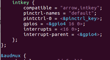

그림 5.7 device tree - intkey, pinctrl_key node 추가 모습
위의 device tree 내용 중, interrupt 관련 부분은 아래와 같은 내용에 입각하여 설정된 것임을 알 수 있다.
intc(GIC) <------- GPIO4 controller <------- gpio button
(interrupt-parent) (interrupt device)
----------------------------------------------------------------------------------------------------------
interrupt-parent 속성: interrupt controller(여기서는 gpio4)에 대한 phandle 값
interrupts 속성: interrupt signal을 내보내는 device(gpio pin/pad)의 pin 값과, IRQ type(include/dt-bindings/interrupt-controller/irq.h 내용 참조) 지정
interrupt-controller 속성: interrupt signal을 받는 interrupt controller임의 의미함.
interrupt-cells 속성: interrupt 속성에서의 cell의 갯수를 지정, 이 내용에 의해 그림 5.7의 interrupts = <16 0>의 내용이 2개의 항목(각각 16과 0)으로 표현되게 됨.
----------------------------------------------------------------------------------------------------------
<driver code>

그림 5.8 intkey.c 코드 내용 중 일부
위의 코드에서 한가지 재밌는 부분은 devm_request_irq() 함수에 넘겨줄 IRQ number를 알아내는 방법이 아래와 같이 2가지가 존재한다는 것이다.
----------------------------------------------------------------------------------------------------------------
방법 1) gpio number를 직접 계산한 후 사용하는 방법
gpio_nb = of_get_gpio(pdev->dev.of_node, 0); /* GPIO4_16 => 92번 */
irq = gpio_to_irq(gpio_nb); /* 92번 gpio pin -> 151 irq 획득 */
방법 2) device tree 내용을 활용하는 방법
irq = platform_get_irq(pdev, 0); /* device tree 내용으로 부터 151 irq 획득 */
----------------------------------------------------------------------------------------------------------------
여기서 잠깐 ! devm_request_irq( ) 함수에 대해...
int devm_request_irq(struct device *dev,
unsigned int irq,
irq_handler_t handler,
unsigned long irq_flags,
const char *devname,
void *dev_id);
=> interrupt handler를 등록한다.
=> 기존에 많이 사용하던 request_irq( ) 함수와 비교해, 첫번째 argument가 struct device pointer라는 점에서 차이가 있는데, 이런 함수를 일컬어 managed resource API(workqueue로 유명한 허태준씨가 2007년 kernel 2.6.21부터 제안함)라고 부른다.
=> 자세한 사항은 참고문헌 [10]을 참고하기 바란다.
- dev: device나 module이 해제될 때에 자동으로 제거되는 장치에의 pointer
- irq: IRQ number. platform device의 경우는 platform_get_irq() 함수를 통해 얻은 값을 사용하면 됨.
- handler: IRQ handler 함수 pointer
- irq_flags: IRQ flag 값(아래 값을 사용할 수 있음)
#define IRQF_TRIGGER_NONE 0x00000000
#define IRQF_TRIGGER_RISING 0x00000001
#define IRQF_TRIGGER_FALLING 0x00000002
#define IRQF_TRIGGER_HIGH 0x00000004
#define IRQF_TRIGGER_LOW 0x00000008
#define IRQF_TRIGGER_MASK (IRQF_TRIGGER_HIGH | IRQF_TRIGGER_LOW | \
IRQF_TRIGGER_RISING | IRQF_TRIGGER_FALLING)
#define IRQF_TRIGGER_PROBE 0x00000010
- devname: interrupt를 위해 사용하는 이름(/proc/interrupts로 확인 가능)
- dev_id: device별 data structure를 가리키는 pointer를 전달하기 위해서 사용함.
-------------------------------------------------------------------------------------------------------------------
<driver 실행>
=> push button을 누를 때마다 interrupt가 발생하고, 아래와 같은 kernel message가 출력된다.

그림 5.9 intkey.ko 동작 모습
# cat /proc/interrupts
=> interrupt name SW5 행 주목 !
=> irq 값이 151임을 알 수 있다.

그림 5.10 intkey.ko 동작 모습 - /proc/interrupts
5.2 GPIO lib를 사용한 interrupt(device tree와 연계) 예제
gpiolib kernel framework을 사용한 driver 예제는 이미 이전 posting에서 여러 차례 다루어 보았으니, 여기서는 반복해서 설명하지 않도록 하겠다.
6. Input subsystem driver 예제 소개
Input subsystem을 사용하는 accelerometer, magnetometer 및 gyroscope 센서를 위한 device tree & device driver 관련 코드는 이미 이전 posting(아래 link 5절)에서 자세히 언급한 바 있다.
따라서 이번 절에서는 참고 문헌[1]에 나와 있는 관련 코드를 언급하는 선에서 마무리하고자 한다.
Input subsystem과 관련해서는 아래 내용을 참조해 주기 바란다.
1) https://github.com/ChunghanYi/linux_kernel_hacks/blob/master/android_kernel_hacks/AndroidKernelHacks_Chapter6.pdf - Chapter 3
2) Essential Linux Drivers (book) - Chapter 7
3) 참고 문헌 [8]

그림 6.1 Input subsystem 구조(참고문헌 [8]에서 발췌)
7 Industrial I/O(IIO) subsystem driver 예제 소개
7.1 IIO subsystem(framework)의 개요
IIO subsystem은 각종 sensor를 위한 driver framework으로 2009년 부터 Jonathan Cameron에 의해 구현되기 시작하였다. IIO subsystem이 존재하기 전에는 부적절하게도 input subsystem과 hwmon subsystem 등이 이를 대신하고 있었으므로, 최근에는 각종 sensor driver가 모두 IIO subsystem으로 교체되고 있는 추세이다. 대표적인 한 예로 smart phone에 들어가는 각종 sensor의 경우 대부분 input subsystem을 활용하여 구현되어 있는데, 이들도 모두 IIO subsystem으로 교체되어야만 하는 상황이다(실제 교체되고 있는지도 모르겠음). 6절에서 언급한 세가지 센서의 경우도 (예전에 구현된 탓에)실은 input subsystem을 근간으로 구현되어 있는게 사실이다.
아무튼, IIO subsystem이 대상으로하는 대표적인 sensor 혹은 그에 상응하는 device를 열거해 보면 다음과 같이 무수히 많다.
- ADC(analog to digital converter), DAC(digital to analog converter)
- accelerometers
- magnetometers
- gyroscopes
- pressure
- humidity
- temperature
- light and proximity
- activity
- chemical
- heart rate monitors
- potentiometers and rheostats
...
IIO subsystem은 참고 문헌 [6], [7]에 그 개념이 상세히 정리되어 있으므로 자세한 사항(특히 data structure 및 kernel API 등)은 이를 참조하는 것으로 하고, 여기서는 지면 관계상 몇장의 그림을 나열하고 넘어가는 것으로 한다.

그림 7.1 IIO subsystem 구조(참고문헌 [7]에서 발췌)

그림 7.2 IIO subsystem event 전달 경로(참고문헌 [7]에서 발췌)

그림 7.3 IIO subsystem을 사용하는 device driver의 기본 구조(참고문헌 [6]에서 발췌)

그리 7.4 IIO device와 주변 system 간의 관계도(참고문헌 [7]에서 발췌)
자, 그럼 이제 부터는 IIO subsystem을 사용하는 실제 예제 코드를 분석해 보도록 하자.
먼저 그림 7.5는 IIO subsystem 예제를 위해 사용되는 eval board로 LTC2607이라는 DAC 장치와 LTC2422이라는 ADC 장치가 각각 장착되어 있다.
-------------------------------------------------------------------------------------------------------------
LTC2607 DAC
=> 여러가지 다른 voltage level을 출력하는데 사용되는 장치(digital -> analog)
=> i2c interface 사용
LTC2422 ADC: LTC2607이 출력하는 voltage level을 읽어 들이는 장치(analog -> digital)
=> spi interface 사용
참고: Analog를 Digital로 바꾸는것을 ADC(Analog to Digital Converter)라 하고 Digital을 Analog로 바꾸는것을 DAC(Digital to Analog Converter) 라고 한다.
-------------------------------------------------------------------------------------------------------------
RIoT board <-> I2C <-> LTC2607
|
| voltage level(analog)
V
RIoT board <-> SPI <-> LTC2422

그림 7.5 Linear Technology DC934A eval 보드(LTC2607 DAC, LTC2422 ADC)
한가지 아쉬운 점은 위의 eval board를 확보하지 못한 관계로, 실제 동작을 확인하지는 못했다는 점이다. 따라서 아래 내용은 실제 동작 내용을 확인하지 못한 상태에서 driver의 전체 구조를 설명하는데 촛점을 맞추었음을 이해하기 바란다.
7.2 I2C를 사용하는 센서 예제
<device>
LTC2607 : dual 12bit, 2.7V to 5.5V rail-to-rail voltage output DAC
<device tree>

그림 7.6 device tree - ltc2607 관련 2개의 node 정의
여기서 reg = <0x72>, reg = <0x73>은 두개의 i2c device 각각의 주솟 값을 의미한다.
<driver code>

그림 7.7 LTC2607_dual_device.c 코드 일부
이해를 돕기 위해 위해 드라이버 code의 주요 흐름을 아래에 정리해 보았다.
a) header file을 추가한다.
# include <linux/i2c.h>
b) struct i2c_driver 구조체를 선언한다.
static struct i2c_driver ltc2607_driver = {
.driver = {
.name = LTC2607_DRV_NAME,
.owner = THIS_MODULE,
.of_match_table = dac_dt_ids,
},
.probe = ltc2607_probe,
.remove = ltc2607_remove,
.id_table = ltc2607_id,
};
c) i2c bus에 i2c driver를 등록한다.
module_i2c_driver(ltc2607_driver);
d) ltc2607(node)를 device list에 추가한다.
static const struct of_device_id dac_dt_ids[] = {
{ .compatible = "arrow,ltc2607", },
{ }
};
MODULE_DEVICE_TABLE(of, dac_dt_ids);
e) i2c_device_id 구조체 배열을 정의한다.
static const struct i2c_device_id ltc2607_id[] = {
{ "ltc2607", 0 },
{ }
};
MODULE_DEVICE_TABLE(i2c, ltc2607_id);
<IIO device driver probe 절차>
a) devm_iio_device_alloc( ) 함수를 호출하여, IIO device를 위한 memory를 할당한다.
b) driver specific information(예를 들어, device name, device channels ..)를 가지고 IIO device fields를 초기화한다.
c) devm_iio_device_register( ) 함수를 호출하여, IIO core에 IIO device를 등록한다.
=> 이제부터는 IIO device는 user space application으로 부터의 요청을 받을 수 있는 준비 상태가 된다.
<application code>
아래 코드는 LTC2607이 대상이 아니라, LTC2422로 부터 값을 읽어 들어는 application 코드에 해당한다.
LTC2607 -> (analog voltage) -> LTC2422 -> /dev/spidev0.0 -> this application(user space)
7.3 SPI를 사용하는 센서 예제
<device>
LTC2422 : 20‐bit ADC for monitoring DAC output voltage
<device tree>

그림 7.8 device tree - ltc2422 관련 node 정의
위의 device tree 내용 중, SPI 설정과 관련된 부분을 정리해 보면 다음과 같다.
------------------------------------------------------------------------------------------------------------
compatible 속성 : SPI device의 이름 지정
reg 속성 : chip select 주소를 지정한다. 위의 경우는 0으로 설정했음.
spi-max-frequency 속성 : SPI device의 maximum clock speed(Hz 단위) 지정, 여기서는 2000000(hexa 값임)을 지정함.
------------------------------------------------------------------------------------------------------------
<driver code>

그림 7.9 LTC2422_dual.c 코드 중 일부
<application code>
아래 파일은 /sys/bus/iio/devices/iio:device2/out_voltage0_raw를 통해 volatage level 값을 읽어드리는 application 코드이다.
https://github.com/ChunghanYi/linux_kernel_hacks/blob/master/linux_driver_development_by_alberto/lab09/LTC2422_app.c
(*) 지면 관계상 추가로 정리하지 못한 내용과 관련해서는 참고문헌 [1]을 참조해 주기 바란다.
8. 맺음말
요즘은 100$ 미만의 값싼 보드(Single Board Computer - 예: Raspberry Pi, BBB ...)를 주변에서 쉽게 찾아 볼 수 있는 세상이 되었다. 이는 다시 말하자면 linux kernel & device driver programming을 실습할 수 있는 환경을 찾는 것도 그만큼 쉬워졌다는 얘기가 된다.지금부터는 모두가 그토록 꿈꿔오던(?) linux master가 되는 (어디에도 없는) 비법을 전수해 주도록 하겠다.
<Linux Master Jedi가 되는 길>

원래 주인공은 이 분이다 ! 내가 니 아빠당~
1) 값싼 보드를 하나 구매하자. Linux가 돌아간다면 어떤 것도 괜찮다.
=> 보드를 사라고 하니까, 꼭 이런 분들 계신다. 아래 보드는 $100도 훌쩍 넘는다. 바닷가에 살고 있는 분이 아니라면 권하고 싶지 않다.

2) 관련 datasheet, schematic(회로도)를 철저히 살펴 본다.
=> 이게 늘 문제다. 처음 한번만 보고 말것이 아니므로, 반복해서 봐야 한다. 왜 한글로 된 datasheet는 없는 거냐 ?
=> 그렇다고 아래와 같은 비행기 회로도(설계도)를 보고 있으면 안된다.

3) 자신이 원하는 적절한 개발 환경(Yocto, buildroot, OpenWRT, Android 등)을 꾸며 본다.
=> 실제로 작업 환경을 꾸미는 일도 우습게 볼 일이 아니다.
=> Programming을 위해서는 editor(예: vi), gcc, make, version control tool(예: git), Ubuntu or Fedora 등 익숙해져야 할 것이 한두가지가 아니다. 여기에 요즘 유행하는 Yocto(욕나오고 토나와서 욕톤가 ?)나 Android(앵~드로이드)까지 파악하려면 머리가 지끈 아파온다. 마치 아래와 같은 복잡한 수학 문제라도 풀어야 할 듯이... 근데, 이대목에서 아래 공식을 굳이 이해하려고 들지 말자 ! 😭

4) 앞서 언급한 내용을 토대로 직접 kernel & device driver programming을 해 본다.
=> 이때 good reference book(예: LDD3, Essential LDD, LKD ...)을 참조하는 것도 도움이 된다. 근데 왜 LDD4 book은 나온다고 해놓고 안나오냐(갑자기 흥분해서 반말을 ...)?
=> free-electrons guy들이 작성한 문서도 훌륭하다(요즘은 이분들이 대세인 듯 보인다).
하지만, 현실은 언제나 그렇게 녹녹하지 만은 않다. 내게 주어지는 문제는 항상 복잡/미묘하기 마련이고, 해답은 위에서 언급한 내용(전형적인 내용) 어디에도 없는 경우가 대부분이다.
그도 그럴것이 Graphics, Display, Audio(sound), Camera(V4L2), Wi-Fi, BT(BLE), network(wired), 각종 sensors .. 해야할게 참으로 많다.

5) 정리하는 습관을 가지는 것도 효과적인 방법이다. 천리길도 한걸음 부터다 !
=> 본 blogger 처럼 내용을 정리해서 blog에 올려 보는 것도 괜찮고, ppt 문서를 작성해도 좋겠다.
=> (꼭 시중에 팔려는 목적이 아녀도 좋으니)책을 써 보는 것도 좋다. 뭣이라고요 ?
=> 정리를 하다 보면, 머릿속에서 내용이 자연스럽게 정리가 된다.

6) 늘 kernel source를 가까이 하라. 모든 답은 kernel source 안에 있다 ! 이거 말고는 특별한 방법이 없다.
=> 속았다. 여기까지 읽었는데 특별한 방법이 없다고 T T
=> 정답이 어디에 있겠는가 ? 열공만이 답일 뿐 ! code를 분석하고 또 분석하자 ...

May the source be with you
(소스가 그대와 함께 하길 ~)
주: 위에서 사용한 이미지는 인터넷에 그냥 가져온 것임. 문제가 되는 부분이 있다면 내리도록 하겠음.
기분전환 차원에서 맺음말을 재밌게(나만 재밌나 ?) 구성해 보았다. 그냥 웃고 넘어가 주시길 ~
References
1. Linux driver development for embedded processors, Alberto Liberal, Circulo Rojo.
=> 첫판이라서 그런지 편집 상태(오탈자, 그림 등)는 형편 없으나, 최신 linux driver관련 issue를 담고 있는 매우 의미 있는 책으로 보임.
2. Embedded Linux Projects Using Yocto Project Cookbook, Alex Gonzalez, PACKT Publishing.
=> yocto project 관련 issue 사항을 이해하기 쉽게 가장 잘 표현한 책
3. Embedded Linux Systems with the Yocto Project, Rudolf J. Streif, Prentice Hall.
=> yocto project 관련하여 깊게 잘 정리한 책
4. IMX-6Solo-Processor-Reference-Manual.pdf, Freescale Semiconductor, Inc.
5. RIoTboard-Schematics-v1.0.pdf, Embest Tech Co., LTD.
6. IIO, a new kernel subsystem, Maxime Ripard, Free Electrons.
7. Industrial I/O Subsystem: The Home of Linux Sensors, Daniel Baluta, Intel
8. linux-kernel-slides.pdf, Free-Electrons.
=> 최신 linux kernel & device driver를 가장 잘 표현한 문서이다. 앞으로 이 문서를 띄어넘는 더 훌륭한 kernel & driver 관련 책이 나올 수 있을지 의심스럽다.
9. https://lwn.net/Kernel/LDD3/
=> linux device drivers, 3rd edition
10. The Right Way: Managed Resource Allocation in Linux Device Drivers, Eli Billauer
Slowboot
내용 잘 보고 갑니다. ^^
답글삭제좋은글 감사합니다. 잘보고있습니다.
답글삭제잘보고 있는데 공들인 내용에 비해 사람들 관심들이 별로 없어보이는것같아 아쉽네요.저변이 넓어야 이런 글들이 빛을 더 발할텐데 암튼 수고하십니다.
답글삭제좋은 정보 감사합니다.
답글삭제정말 훌륭하십니다 블로그 내용 책으로 출간하시면 사고싶네요
답글삭제어려운 내용 쉽게 풀어주셔서 감사해요~~ 책으로 나오면 좋겠네요
답글삭제궁금했던 많은 문제를 한 번에 알게되었네요.
답글삭제감사합니다.
안녕하세요.
답글삭제Embedded Linux에 대해서 궁금한게 있어 문의 드립니다.
아래 사양을 가지고 포팅 및 개발을 하려 하는데 가능할까요?
혹시 포팅이 어렵다면 잘하는 업체를 끼고 해야 할까요?
포팅 비용도 대략 궁금합니다.
초면에 이런 질문으 드려 죄송합니다. 알아볼곳이 없어서 -_-;;
CPU: i.Mx 6 Solo (800MHz)
OS: Embedded Linux
개발도구: Qt5
3D Graphics Accelerator: OpenGL-ES
블로그 관리자가 댓글을 삭제했습니다.
답글삭제