2017년 2월 28일 화요일

Efficient Linux Kernel 4.x Programming Techniques - Part 1

이번 posting에서는 아래 참고 문헌(References 내용)을 토대로 최신 kernel 4.x version에 적용 가능한 몇가지 linux kernel programming 기법을 소개 [첫번째 시간]하는 시간을 갖고자 한다. 아래 내용을 원할하게 이해하기 위해서는 (5년전에 작성한 내용이기는 하지만) 본 저자가 작성한 아래 파일 내용도 함께 참조해 주기 바란다.


<목차>
1. Target Board(UDOO Neo) 환경 소개
2. Kernel Timer 예제 소개
3. Interrupt & Tasklet 예제 소개
4. Threaded Interrupt 예제 소개
5. Interrupt & workqueue 예제 소개
6. Kernel Thread 예제 소개


1. Target Board(UDOO Neo) 환경 소개
Linux kernel 예제 program을 돌리기 위한 target board로는 UDOO Neo를 이용할 계획이고, kernel 및 rootfs 등은 buildroot를 통해 구성할 생각이다. 따라서 이번 절에서는 먼저 buildroot를 기반으로 UDOO Neo board를 부팅(NFS)하는 방법을 소개하고자 한다.

git clone git://git.buildroot.net/buildroot
  => buildroot 최신 버젼을 내려 받는다.

$ cd buildroot

make mx6sx_udoo_neo_defconfig
  => buildroot 최신 버젼에는 이미 udoo neo 보드용 config가 준비되어 있다.

make menuconfig
  => glibc를 enable하도록 수정한다. 추가로 원하는 내용이 있다면 반영하도록 한다.

make

<결과물>
chyi@earth:~/buildroot/output/images$ ls -la
합계 47556
drwxr-xr-x  3 chyi chyi     4096  2월 23 19:14 .
drwxrwxr-x  6 chyi chyi     4096  2월 22 11:51 ..
-rw-r--r--  1 chyi chyi    48128  2월 22 14:02 SPL
-rw-r--r--  1 chyi chyi    29277  2월 22 14:07 imx6sx-udoo-neo-basic.dtb
-rw-r--r--  1 chyi chyi    29098  2월 22 14:07 imx6sx-udoo-neo-extended.dtb
-rw-r--r--  1 chyi chyi    29277  2월 22 14:07 imx6sx-udoo-neo-full.dtb
-rw-r--r--  1 chyi chyi 15972352  2월 22 14:07 rootfs.ext2
lrwxrwxrwx  1 chyi chyi       11  2월 22 14:07 rootfs.ext4 -> rootfs.ext2
-rw-r--r--  1 chyi chyi 12410880  2월 22 14:07 rootfs.tar
-rw-r--r--  1 chyi chyi 17020928  2월 22 14:07 sdcard.img
-rwxr-xr-x  1 chyi chyi   237376  2월 22 14:02 u-boot.bin
-rw-r--r--  1 chyi chyi   237440  2월 22 14:02 u-boot.img
-rw-r--r--  1 chyi chyi  6173896  2월 22 14:07 zImage

cd output/images
mkdir rootfs; sudo tar xvf ./rootfs.tar -C ./rootfs
  => rootfs.tar의 압축을 푼다.

cp ./zImage /tftpboot
cp ./imx6sx-udoo-neo-full.dtb /tftpboot
  => NFS booting을 위해 zImage와 dtb 파일을 /tftpboot로 복사한다.

vi /etc/exports
...
~/IoT/UDOO/src/buildroot/output/images/rootfs 192.168.1.*(rw,no_root_squash,sync,no_subtree_check)
~
  => /etc/exports 파일에 buildroot rootfs의 path를 설정해 준다.

sudo /etc/init.d/nfs-kernel-server restart
  => nfs server를 재구동시킨다.

Buildroot가 정상적으로 build되었고, NFS booting을 위한 설정이 마무리 되었으니, 이제는 target board의 u-boot 설정을 변경하도록 하자.

<Target board - u-boot>
=> setenv ipaddr 192.168.1.50
=> setenv serverip 192.168.1.100
=> setenv netmask 255.255.255.0
=> ping 192.168.1.100
Using FEC0 device
host 192.168.1.100 is alive

=> setenv rootpath /home/chyi/IoT/UDOO/src/buildroot/output/images/rootfs
=> setenv nfsboot 'setenv bootargs root=/dev/nfs rw nfsroot=${serverip}:${rootpath} ip=${ipaddr}:${serverip}::${netmask}::eth0:off noinitrd console=ttymxc0,115200; tftp 0x80000000 zImage; tftp 0x86000000 imx6sx-udoo-neo-full.dtb; bootz 0x80000000 - 0x86000000'
  (*) 특이한 점은 noinitrd를 포함시켜야 한다는 점임.

=> run nfsboot


2.  Kernel Timer 예제 소개
이번 절에서는 몸풀기 단계로, kernel timer를 사용하는 간단한 예제를 소개해 보도록 하겠다. Kernel timer(혹은 dynamic timer)는 지정된 timer interval이 경과할 때가지 함수 실행을 지연시킬 필요가 있을 경우(쉽게 말해, 일정한 시간 간격을 두고 특정 함수를 실행)에 주로 사용된다.

2.1 Multiple Periodic Kernel Timers 예제(2개의 timer를 동시에 돌리는 예제)
-------------------------------------------------------------------------------------------------------------------------------------------------------------------
<lab4_periodic_timers_alt.c>
/*
 * The code herein is: Copyright Jerry Cooperstein, 2012
 *
 * This Copyright is retained for the purpose of protecting free
 * redistribution of source.
 *
 *     URL:    http://www.coopj.com
 *     email:  coop@coopj.com
 *
 * The primary maintainer for this code is Jerry Cooperstein
 * The CONTRIBUTORS file (distributed with this
 * file) lists those known to have contributed to the source.
 *
 * This code is distributed under Version 2 of the GNU General Public
 * License, which you should have received with the source.
 *
 */

#include <linux/module.h>
#include <linux/timer.h>
#include <linux/init.h>
#include <linux/jiffies.h>
#include <linux/slab.h>

static struct my_data {   /* 아래 예제를 위해 만든 data structure - 한번에 두개의 timer를 돌리고자 함 */
unsigned long period;   /* timer function이 호출되는 주기 */
unsigned long start_time; /* timer 시작 시간: jiffies */
struct timer_list timer;  /* timer 선언include/linux/timer.h에 정의되어 있음 */
char struct_id; /* 두개의 timer를 구분하기 위한 id : 'A' or 'B' */
} *data_array; /* will kmalloc() an array of these */

static void my_timer_func(unsigned long var)   /* timer 기간 만료시 실행되는 함수 */
{
  struct my_data *dat = (struct my_data *)var;   /* 전달받은 argument를  struct my_data* type으로 casting */

pr_info("%c: period = %ld  elapsed = %ld\n", dat->struct_id, dat->period, jiffies - dat->start_time);
dat->start_time = jiffies;  /* timer 시작 시간 지정 */

mod_timer(&dat->timer, dat->period + jiffies);  /* timer가 만료되는 시간을 다시 초기화한다 */
}

static int __init my_init(void)  /* module을 시작한다 */
{
int i, period_in_secs;
struct my_data *d;

data_array = kmalloc(2 * sizeof(struct my_data), GFP_KERNEL);  /* struct my_data kernel memory 2개 할당 */

for (d = data_array, i = 0; i < 2; i++, d++) {
init_timer(&d->timer);  /* linked list의 previous, next pointer를 0으로 초기화 시킨다 */

period_in_secs = (i == 0) ? 1 : 10;
d->period = period_in_secs * HZ;  /* timer function이 호출되는 주기를 설정함. A timer: 1Hz, B timer: 10Hz로 지정 */
d->struct_id = 'A' + i;   /* A, B timer id */
d->start_time = jiffies;  /* timer 시작 시간 지정 */
d->timer.function = my_timer_func;  /* timer 만료 시 실행될 함수를 지정함 */
d->timer.expires = jiffies + d->period;  /* timer가 만료되는 시간 값을 지정함 - jiffie로 측정하는 절대 값임 */
d->timer.data = (unsigned long)d;  /* timer function에 전달할 argument를 지정함 */

add_timer(&d->timer);  /* global timer list에 새로운 timer를 추가함 */
}
pr_info("Module loaded, two timers started\n");
return 0;
}

static void __exit my_exit(void)  /* 모듈을 종료한다 */
{
int i;
struct my_data *d = data_array;
for (i = 0; i < 2; i++, d++) {
pr_info("deleted timer %c:  rc = %d\n", d->struct_id, del_timer(&d->timer));  /* timer 시간이 만료되기 전에 timer를 제거한다 */
}
kfree(data_array);  /* my_init()에서 할당했던  kernel memory를 해지한다 */
pr_info("Module unloaded\n");
}

module_init(my_init);
module_exit(my_exit);

MODULE_AUTHOR("Jerry Cooperstein");  /* 참고 문헌 [1]의 저자가 작성한 코드임 */
MODULE_AUTHOR("Bill Kerr");
MODULE_DESCRIPTION("LDD:2.0 s_11/lab4_periodic_timers_alt.c");
MODULE_LICENSE("GPL v2");
-------------------------------------------------------------------------------------------------------------------------------------------------------------------

참고로 아래 내용은 include/linux/timer.h에 정의되어 있는 struct timer_list의 실제 내용을 보여준다.

struct timer_list {
    /*
     * All fields that change during normal runtime grouped to the
     * same cacheline
     */
    struct hlist_node   entry;  /* struct hlist_node *next, **pprev를 담고 있음 */
    unsigned long       expires;
    void            (*function)(unsigned long);
    unsigned long       data;
    u32         flags;

#ifdef CONFIG_TIMER_STATS
    int         start_pid;
    void            *start_site;
    char            start_comm[16];
#endif
#ifdef CONFIG_LOCKDEP
    struct lockdep_map  lockdep_map;
#endif
};

-------------------------------------------------------------------------------------------------------------------------------------------------------------------
<Makefile>
obj-m +=  lab4_periodic_timers_alt.o
export KROOT=/home/chyi/IoT/UDOO/src/buildroot/output/build/linux-4.9  /* buildroot에 포함한 linux kernel 4.9의 위치 지정 */
export ARCH=arm

allofit:  modules
modules:
    @$(MAKE) -C $(KROOT) M=$(PWD) modules
modules_install:
    @$(MAKE) -C $(KROOT) M=$(PWD) modules_install
kernel_clean:
    @$(MAKE) -C $(KROOT) M=$(PWD) clean

clean: kernel_clean
    rm -rf   Module.symvers modules.order
-------------------------------------------------------------------------------------------------------------------------------------------------------------------

<How to compile>
$ export KROOT=/home/chyi/IoT/UDOO/src/buildroot/output/build/linux-4.9
$ export ARCH=arm
$ export CROSS_COMPILE=arm-linux-
$ export CC=arm-linux-gcc
$ export PATH=/home/chyi/IoT/UDOO/src/buildroot/output/host/usr/bin:$PATH
  => cross compile을 위한 환경 변수를 지정한다.

$ make
  => build하여 kernel module을 생성해 낸다.

$ sudo cp ./lab4_periodic_timers_alt.ko ~/IoT/UDOO/src/buildroot/output/images/rootfs/modules
  => build 결과물을 rootfs(NFS booting 용)의 적당한 위치로 복사한다.

<How to run it on the target board>
  => target board에서 실행한 결과는 다음과 같다.
# insmod ./lab4_periodic_timers_alt.ko 
[   33.083943] lab4_periodic_timers_alt: loading out-of-tree module taints kernel.
[   33.092944] Module loaded, two timers started
# [   34.171546] A: period = 100  elapsed = 108

# [   35.211081] A: period = 100  elapsed = 104
[   36.251044] A: period = 100  elapsed = 104
[   37.291056] A: period = 100  elapsed = 104
[   38.331037] A: period = 100  elapsed = 104
[   39.371047] A: period = 100  elapsed = 104
[   40.411067] A: period = 100  elapsed = 104
[   41.451044] A: period = 100  elapsed = 104
[   42.491065] A: period = 100  elapsed = 104
[   43.371035] B: period = 1000  elapsed = 1028
[   43.531028] A: period = 100  elapsed = 104
[   44.571067] A: period = 100  elapsed = 104
[   45.611060] A: period = 100  elapsed = 104
  => A, B 두개의 timer가 1HZ(100), 10HZ(10*100) 간격으로 호출되고 있음을 알 수 있다.

2.2 High resolution timer 예제
hrtimer는 nanosecond를 단위로 보다 세밀하게(정교하게) timer를 설정하는 방법으로 2.6.16 kernel 부터 도입되기 시작하였다. hrtimer는 CPU 당 1개의 list(timer 만료 시간을 기준으로 정렬된 list)가 존재하는 특징이 있다. hrtimer를 이해하기 위해서는 ktime_t(include/linux/ktime.h)를 살펴볼 필요가 있다.
-------------------------------------------------------------------------------------------------------------------------------------------------------------------
<lab5_hrtimer.c>
#include <linux/module.h>
#include <linux/kernel.h> /* for container_of */
#include <linux/timer.h>
#include <linux/init.h>
#include <linux/ktime.h>
#include <linux/hrtimer.h>
#include <linux/slab.h>

static struct my_data {  /* 아래 예제 코드를 위해 정의된 data structure */
ktime_t period;   /* timer interval */
int period_in_secs;
unsigned long start_time; /* timer 시작 시간: jiffies */
struct hrtimer timer;  /* hrtimer 변수 선언 */
char struct_id; /* 두개의 timer를 구분하기 위한 id 값 : 'A' or 'B' */
} *data_array; /* will kmalloc() an array of these */

static enum hrtimer_restart my_timer_func(struct hrtimer *var)  /* timer 만료시 호출되는 함수 */
{
struct my_data *dat = container_of(var, struct my_data, timer);  /* 넘어온 argument(var)와 timer element를 토대로 struct  my_data의 시작 주소를 역산한 후, type casting하여 struct my_data의 pointer를 얻어내는 함수 */
ktime_t now;

pr_info("%c: period = %d  elapsed = %ld\n", dat->struct_id, dat->period_in_secs, jiffies - dat->start_time);

now = var->base->get_time();  /* clock으로 부터 현재 시간을 얻어 옴 */
dat->start_time = jiffies;   /* timer 시작 시간 지정 : jiffies(현재 시간으로 보면 됨) */
hrtimer_forward(var, now, dat->period);   /* timer 만료 시간을 reset해 준다 */
return HRTIMER_RESTART;   /* timer 반복을 의미함. 한편, HRTIMER_NORESTART를 return할 경우에는, timer가 1회만 실행하고 멈추게 됨 */
}

static int __init my_init(void)
{
int i;
struct my_data *d;

data_array = kmalloc(2 * sizeof(struct my_data), GFP_KERNEL);  /* struct my_data 크기의 kernel 영역 2개 확보 */

for (d = data_array, i = 0; i < 2; i++, d++) {
d->period_in_secs = (i == 0) ? 1 : 10;  /* A timer 는 1, B timer는 10 선택 */
d->period = ktime_set(d->period_in_secs, 0);  /* seconds/nanoseconds 값으로 ktime_t 변수 설정함 */
d->struct_id = 'A' + i;  /* 2개의 timer 각각에 id 할당, 즉 A, B */

hrtimer_init(&d->timer, CLOCK_REALTIME, HRTIMER_MODE_REL);  /* time를 초기화한다. HRTIMER_MODE_REL:  now 시간에 대한 상대 시간을 의미함 */

d->timer.function = my_timer_func;  /* timer 함수 지정 */
d->start_time = jiffies;   /* timer 시작 시간 지정 : jiffies(현재 시간으로 보면 됨)*/

hrtimer_start(&d->timer, d->period, HRTIMER_MODE_REL);  /* current CPU 상에서 hrtimer를 시작한다 */
}
pr_info("Module loaded, two HRTimers started\n");

return 0;
}

static void __exit my_exit(void)
{
int i;
struct my_data *d = data_array;

for (i = 0; i < 2; i++, d++) {
pr_info("deleted timer %c:  rc = %d\n",
d->struct_id, hrtimer_cancel(&d->timer));  /* timer를 취소한다. 단, timer function이 종료되기를 기다린다 */
}
kfree(data_array);  /* my_init()에서 할당했던  kernel memory를 해지한다 */
pr_info("Module unloaded\n");
}

module_init(my_init);
module_exit(my_exit);

MODULE_AUTHOR("Jerry Cooperstein");
MODULE_AUTHOR("Bill Kerr");
MODULE_DESCRIPTION("LDD:2.0 s_11/lab5_hrtimer.c");
MODULE_LICENSE("GPL v2");
-------------------------------------------------------------------------------------------------------------------------------------------------------------------
아래 내용은 include/linux/hrtimer.h에 정의되어 있는 struct hrtimer의 definition을 보여준다.

struct hrtimer {
    struct timerqueue_node      node;
    ktime_t             _softexpires;
    enum hrtimer_restart        (*function)(struct hrtimer *);
    struct hrtimer_clock_base   *base;
    u8              state;
    u8              is_rel;
#ifdef CONFIG_TIMER_STATS
    int             start_pid;
    void                *start_site;
    char                start_comm[16];
#endif
};

또한 아래 내용은 include/linux/ktime.h에 정의되어 있는 ktime_t의 실체를 보여주고 있다.

union ktime {
    s64 tv64;
};
 
typedef union ktime ktime_t;        /* Kill this */

<How to run it on the target board>
# insmod ./lab5_hrtimer.ko 
[ 1947.630129] Module loaded, two HRTimers started
# [ 1948.632834] A: period = 1  elapsed = 100
[ 1949.632833] A: period = 1  elapsed = 100
[ 1950.632835] A: period = 1  elapsed = 100
[ 1951.632832] A: period = 1  elapsed = 100
[ 1952.632852] A: period = 1  elapsed = 100
[ 1953.632842] A: period = 1  elapsed = 100
[ 1954.632835] A: period = 1  elapsed = 100
[ 1955.632842] A: period = 1  elapsed = 100
[ 1956.632807] A: period = 1  elapsed = 100
[ 1957.632817] A: period = 1  elapsed = 100
[ 1957.636846] B: period = 10  elapsed = 1000
[ 1958.632819] A: period = 1  elapsed = 100
[ 1959.632832] A: period = 1  elapsed = 100
[ 1960.632827] A: period = 1  elapsed = 100
[ 1961.632829] A: period = 1  elapsed = 100
[ 1962.632837] A: period = 1  elapsed = 100
[ 1963.632832] A: period = 1  elapsed = 100
  => 2.1의 예제와 비교할 때, 정확한 시간(100 or 1000)이 경과한 시점에 timer가 만료되고 있음을 알 수 있다.

3. Interrupt & Tasklet 예제 소개
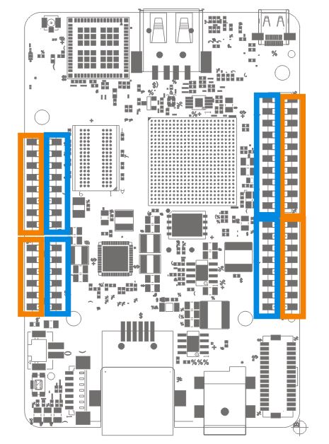
이번 절에서는 UDOO Neo 보드 외부에 bread board를 하나 연결하고, 그 위에 switch 버튼을 장착한 상태에서 switch 버튼이 눌릴 경우(interrupt 발생), interrupt handler 내에서 tasklet이 동작하는 예제 program을 소개해 보고자 한다. Tasklet(상대적으로 개념이 모호한)은 bottom half의 한 종류로 softirq에 기반을 두고 있다. 대표적인 bottom half인 work queue와 비교하면 process context에서 실행되지 않으며, 동일한 CPU에서만 schedule이 진행되는 특징이 있어, cache coherency, serialization 등이 우수한 기법으로 볼 수  있다(간단히 bottom half를 만들 수 있는 편한 방법임).

그림 3.1 UDOO Neo 보드 interrupt 실험 환경 

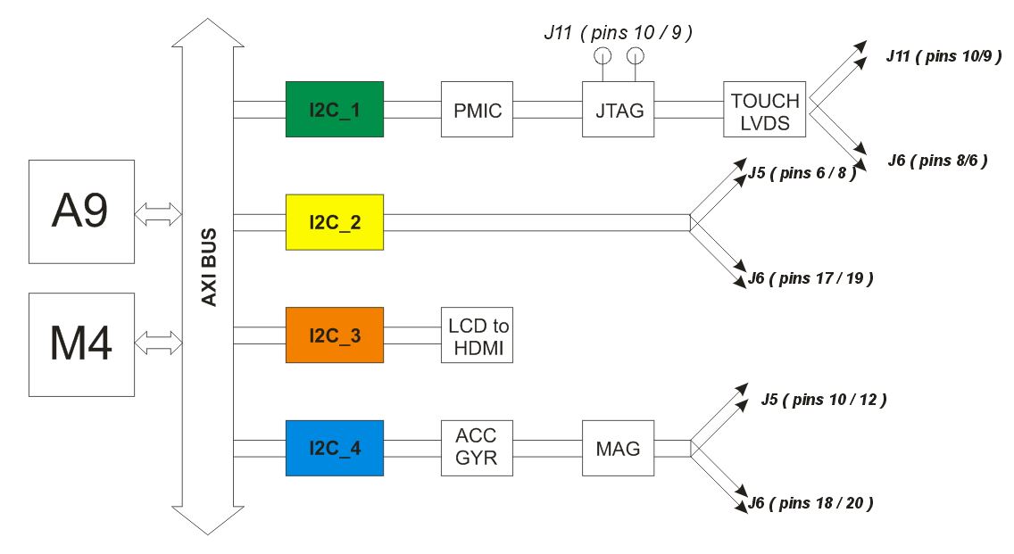
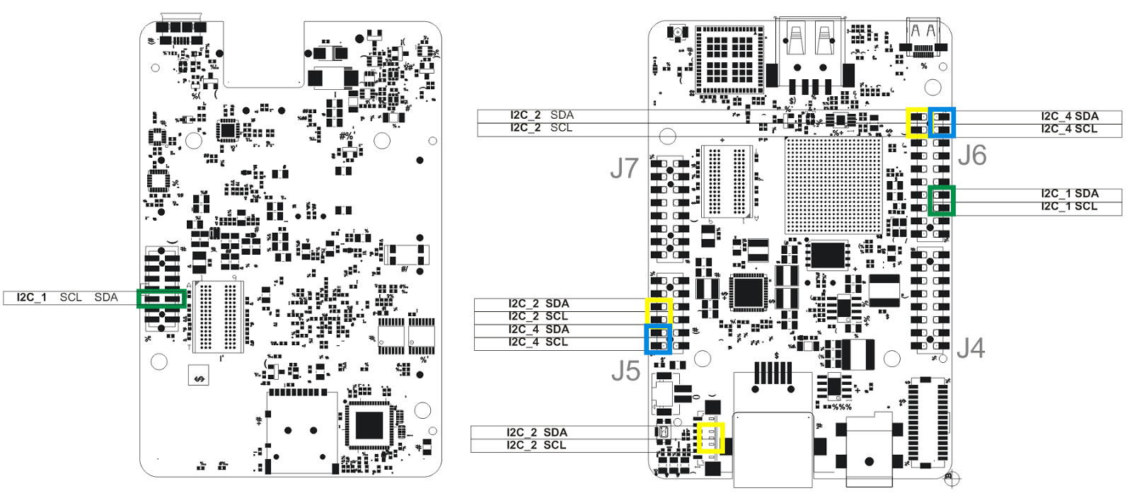
그림 3.2 UDOO Neo 보드 external pinout 배치도

-------------------------------------------------------------------------------------------------------------------------------------------------------------------
<lab_one_interrupt_gpio.h>
#ifndef _LAB_ONE_INTERRUPT_H
#define _LAB_ONE INTERRUPT_H

#include <linux/module.h>
#include <linux/init.h>
#include <linux/interrupt.h>
#include <linux/delay.h>
#include <linux/workqueue.h>
#include <linux/kthread.h>
#include <linux/slab.h>

static int switch_gpio = 180;   /* 그림 3.2 우측 GPIO_180 pin 참조 */
static int irq = 0;
module_param(irq, int, S_IRUGO);

/* default delay time in top half -- try 10 to get results */
static int delay = 0;
module_param(delay, int, S_IRUGO);

static atomic_t counter_bh, counter_th;

struct my_dat {  /* interrupt handler에 넘기는 argument 형식으로 아래 예제에서는 크게 의미 없음 - 다른 예제와 연관이 있는 코드이므로 여기서는 무시하기로 함. 단 jiffies 변수는 사용함. */
unsigned long jiffies; /* used for timestamp */
struct tasklet_struct tsk; /* used in dynamic tasklet solution */
struct work_struct work; /* used in dynamic workqueue solution */
};
static struct my_dat my_data;

static irqreturn_t my_interrupt(int irq, void *dev_id);

static int __init my_generic_init(void)
{
atomic_set(&counter_bh, 0);
atomic_set(&counter_th, 0);

/* use my_data for dev_id */

if (request_irq(irq, my_interrupt, IRQF_TRIGGER_RISING | IRQF_TRIGGER_FALLING,
                 "my_int", &my_data))   /* interrupt handler - my_interrupt() - 등록, RISING or FALLING edge 시 interrupt 발생
                                                        ...................... (A) */
{
pr_warning("Failed to reserve irq %d\n", irq);
return -1;
}
pr_info("successfully loaded\n");
return 0;
}

static void __exit my_generic_exit(void)
{
synchronize_irq(irq);
free_irq(irq, &my_data);  /* interrupt handler 등록 내용 제거 */
pr_info(" counter_th = %d,  counter_bh = %d\n", atomic_read(&counter_th), atomic_read(&counter_bh));
pr_info("successfully unloaded\n");
}

MODULE_AUTHOR("Jerry Cooperstein");
MODULE_AUTHOR("Chunghan Yi");
MODULE_DESCRIPTION("LDD:2.0 s_20/lab_one_interrupt.h");
MODULE_LICENSE("GPL v2");

#endif
-------------------------------------------------------------------------------------------------------------------------------------------------------------------
#include <linux/module.h>
#include "lab_one_interrupt_gpio.h"  /* 위의 파일 */
#include <linux/gpio.h>

static atomic_t nevents; /* number of events to deal with */
static atomic_t catchup; /* number of 'missed events' */

static void t_fun(unsigned long t_arg)   /* tasklet 함수 */
{
struct my_dat *data = (struct my_dat *)t_arg;

/* did we get a spurious interrupt, or was it queued too late? */
if (atomic_read(&nevents) <= 0)   /* nevents 값이 0보다 작으면 바로 return 함 */
return;

for (;;) {
atomic_inc(&counter_bh);   /* counter_bh 값을 1 증가 시킴 */
pr_info
           ("In BH: counter_th = %d, counter_bh = %d, jiffies=%ld, %ld\n",
           atomic_read(&counter_th), atomic_read(&counter_bh),
           data->jiffies, jiffies);
if (atomic_dec_and_test(&nevents))   /* nevents 값을 1감소 시킨 후, 0이면 true를 return */
break;
atomic_inc(&catchup);   /* catchup 값을 1 증가 시킴 */
pr_info("****** nevents > 0, catchup=%d\n", atomic_read(&catchup));
}
}

/* initialize tasklet */
static DECLARE_TASKLET(t_name, t_fun, (unsigned long)&my_data);   /* tasklet 정적 초기화 - my_dat가 t_fun의 argument로 전달됨 */

static irqreturn_t my_interrupt(int irq, void *dev_id)   /* interrupt handler 함수, (A)에서 사용됨 */
{
struct my_dat *data = (struct my_dat *)dev_id;
  atomic_inc(&counter_th);   /* counter_th 값을 1 증가 시킴 */
atomic_inc(&nevents);  /* nevents 값을 1 증가 시킴 */
data->jiffies = jiffies;
tasklet_schedule(&t_name);   /* tasklet 수행 시작 요청 */
mdelay(delay); /* hoke up a delay to try to cause pileup */
return IRQ_NONE; /* we return IRQ_NONE because we are just observing */
}

static int __init my_init(void)
{
    int ret;

atomic_set(&catchup, 0);   /* catchup을 0으로 초기화 */
atomic_set(&nevents, 0);  /* nevents를 0으로 초기화 */

    /* switch_gpio 180(GPIO_180)번 pin을 gpio input으로 사용하겠다고 요청 */
ret = gpio_request_one(switch_gpio, GPIOF_IN, "test button");
if (ret < 0) {
pr_info("failed to request GPIO %d, error %d\n", switch_gpio, ret);
return -1;
}

#if 0  /* 위의 함수에서 GPIOF_IN 파라미터를 넘길 경우, 아래 함수 자동 실행됨 */
ret = gpio_direction_input(switch_gpio);
if (ret < 0) {
pr_info("failed to input GPIO %d, error %d\n", switch_gpio, ret);
return -1;
}
#endif

irq = gpio_to_irq(switch_gpio);  /* gpio line을 interrupt로 사용하도록 해 줌 */
if (irq < 0) {
pr_info("failed to gpio_to_irq() %d\n", irq);
return -1;
}

return my_generic_init();
}

static void __exit my_exit(void)
{
my_generic_exit();
gpio_free(switch_gpio);   /* gpio_request_one  한 내용 해제 */
pr_info("Final statistics:   catchup = %d\n", atomic_read(&catchup));
}

module_init(my_init);
module_exit(my_exit);

MODULE_AUTHOR("Jerry Cooperstein");
MODULE_AUTHOR("Chunghan Yi");
MODULE_DESCRIPTION("LDD:2.0 s_20/lab3_one_tasklet_improved.c");
MODULE_LICENSE("GPL v2");
-------------------------------------------------------------------------------------------------------------------------------------------------------------------

<How to run it on the target board>
# insmod ./lab3_one_tasklet_improved_gpio.ko
[ 9147.234166] gpio_request_one() ok - switch_gpio: 180 !
[ 9147.239687] gpio_to_irq() ok - irq : 238 !
[ 9147.244176] successfully loaded
#
  => button을 누르거나 뗄 경우, 아래 메시지 출력(interrupt 발생 후, tasklet 수행)
# [ 9150.091393] In BH: counter_th = 4, counter_bh = 1, jiffies=885008, 885008
[ 9150.098384] ****** nevents > 0, catchup=1
[ 9150.102458] In BH: counter_th = 4, counter_bh = 2, jiffies=885008, 885009
[ 9150.109409] ****** nevents > 0, catchup=2
[ 9150.113482] In BH: counter_th = 4, counter_bh = 3, jiffies=885008, 885010
[ 9150.120396] ****** nevents > 0, catchup=3
[ 9150.124465] In BH: counter_th = 4, counter_bh = 4, jiffies=885008, 885011
[ 9150.983455] In BH: counter_th = 7, counter_bh = 5, jiffies=885097, 885097
[ 9150.990360] ****** nevents > 0, catchup=4
[ 9150.994396] In BH: counter_th = 10, counter_bh = 6, jiffies=885097, 885097
[ 9151.001288] ****** nevents > 0, catchup=5
[ 9151.005317] In BH: counter_th = 10, counter_bh = 7, jiffies=885097, 885097
[ 9151.012207] ****** nevents > 0, catchup=6
[ 9151.016235] In BH: counter_th = 10, counter_bh = 8, jiffies=885097, 885097
[ 9151.023124] ****** nevents > 0, catchup=7
[ 9151.027151] In BH: counter_th = 10, counter_bh = 9, jiffies=885097, 885097
[ 9151.034039] ****** nevents > 0, catchup=8
[ 9151.038123] In BH: counter_th = 10, counter_bh = 10, jiffies=885097, 885103
[ 9151.363217] In BH: counter_th = 11, counter_bh = 11, jiffies=885135, 885135


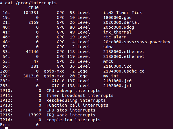
그림 3.3 my_int interrupt handler가 등록된 모습 확인(irq: 238)


4. Threaded Interrupt 예제 소개
이번 절에서는 interrupt 발생 시, 자동으로 kernel thread가 하나 생성된 뒤, 이 곳에서 interrupt 요청을 처리하는 방식인 threaded interrupt 기법에 대해 소개하고자 한다. 실험에 사용된 환경은 그림 3.1과 동일하다.

-------------------------------------------------------------------------------------------------------------------------------------------------------------------
<lab_one_interrupt_gpio_thread.h>
#ifndef _LAB_ONE_INTERRUPT_H
#define _LAB_ONE INTERRUPT_H

#include <linux/module.h>
#include <linux/init.h>
#include <linux/interrupt.h>
#include <linux/delay.h>
#include <linux/workqueue.h>
#include <linux/kthread.h>
#include <linux/slab.h>

static int switch_gpio = 180;    /* 그림 3.2 우측 GPIO_180 pin 참조 */
static int irq = 0;
module_param(irq, int, S_IRUGO);

/* default delay time in top half -- try 10 to get results */
static int delay = 0;
module_param(delay, int, S_IRUGO);

static atomic_t counter_bh, counter_th;

struct my_dat {   /* interrupt handler에 넘기는 argument 형식으로 아래 예제에서는 크게 의미 없음 */
unsigned long jiffies; /* used for timestamp */
struct tasklet_struct tsk; /* used in dynamic tasklet solution */
struct work_struct work; /* used in dynamic workqueue solution */
};
static struct my_dat my_data;

static irqreturn_t my_interrupt(int irq, void *dev_id);
static irqreturn_t thread_fun(int irq, void *thr_arg);

static int __init my_generic_init(void)
{
atomic_set(&counter_bh, 0);
atomic_set(&counter_th, 0);

/* use my_data for dev_id */

if (request_threaded_irq(irq, my_interrupt, thread_fun, IRQF_TRIGGER_RISING | IRQF_TRIGGER_FALLING,
"my_int", &my_data))   /* my_interrupt handler 내에서  IRQ_WAKE_THREAD를 return할 경우, thread_fun가 thread로 실행됨 */
{
pr_warning("Failed to reserve irq %d\n", irq);
return -1;
}
pr_info("successfully loaded\n");
return 0;
}

static void __exit my_generic_exit(void)
{
  synchronize_irq(irq);
free_irq(irq, &my_data);
pr_info(" counter_th = %d,  counter_bh = %d\n", atomic_read(&counter_th), atomic_read(&counter_bh));
pr_info("successfully unloaded\n");
}

MODULE_AUTHOR("Jerry Cooperstein");
MODULE_AUTHOR("Chunghan Yi");
MODULE_DESCRIPTION("LDD:2.0 s_20/lab_one_interrupt.h");
MODULE_LICENSE("GPL v2");


#endif
-------------------------------------------------------------------------------------------------------------------------------------------------------------------
<lab6_one_threaded_gpio.h>
#include <linux/module.h>
#include <linux/version.h>
#include <linux/gpio.h>

#if LINUX_VERSION_CODE < KERNEL_VERSION(2,6,30)
static int __init my_init(void)
{
pr_warning("Threaded interrupts don't appear until 2.6.30\n");
return -1;
}

module_init(my_init)
#else

#define THREADED_IRQ

#include "lab_one_interrupt_gpio_thread.h"    /* 위의 파일 */

static atomic_t nevents;

static irqreturn_t my_interrupt(int irq, void *dev_id)    /* interrupt handler 함수 */
{
atomic_inc(&counter_th);   /* counter_th 1 증가 시킴 */
atomic_inc(&nevents);   /* nevents 1 증가 시킴 */
mdelay(delay); /* hoke up a delay to try to cause pileup */
return IRQ_WAKE_THREAD;   /* 이 값을 return할 경우, handler thread를 깨우고 thread_fun을 실행하게 됨 */
}

static irqreturn_t thread_fun(int irq, void *thr_arg)
{
do {
atomic_inc(&counter_bh);   /* counter_bh 1 증가 시킴 */
}
while (!atomic_dec_and_test(&nevents));   /* nevents를 1 감소 후, 그 값이 0이면 true return ! */
pr_info("In BH: counter_th = %d, counter_bh = %d, nevents=%d\n",
atomic_read(&counter_th), atomic_read(&counter_bh),
atomic_read(&nevents));

/* we return IRQ_NONE because we are just observing */
return IRQ_NONE;
}

static int __init my_init(void)
{
int ret;

atomic_set(&nevents, 0);  /* nevents을 0으로 초기화 */

   /* switch_gpio 180(GPIO_180)번 pin을 gpio input으로 사용하겠다고 요청 */
ret = gpio_request_one(switch_gpio, GPIOF_IN, "test button");
if (ret < 0) {
pr_info("failed to request GPIO %d, error %d\n", switch_gpio, ret);
return -1;
}

#if 0
ret = gpio_direction_input(switch_gpio);
if (ret < 0) {
pr_info("failed to input GPIO %d, error %d\n", switch_gpio, ret);
return -1;
}
#endif

irq = gpio_to_irq(switch_gpio);
if (irq < 0) {
pr_info("failed to gpio_to_irq() %d\n", irq);
return -1;
}

return my_generic_init();
}

static void __exit my_exit(void)
{
    my_generic_exit();
    gpio_free(switch_gpio);
}

module_init(my_init);
module_exit(my_exit);
#endif

MODULE_AUTHOR("Jerry Cooperstein");
MODULE_AUTHOR("Chunghan Yi");
MODULE_DESCRIPTION("LDD:2.0 s_20/lab6_one_threaded.c");

MODULE_LICENSE("GPL v2");
-------------------------------------------------------------------------------------------------------------------------------------------------------------------

# insmod ./lab6_one_threaded_gpio.ko 
[ 2362.187954] successfully loaded
  => switch 버튼을 누르거나 뗄 경우, 아래 메시지(thread_fun 함수에서 아래 내용 출력)가 출력됨.
# [ 2401.757974] In BH: counter_th = 1, counter_bh = 1, nevents=0
[ 2405.693092] In BH: counter_th = 2, counter_bh = 2, nevents=0
[ 2405.856909] In BH: counter_th = 3, counter_bh = 3, nevents=0
[ 2405.882451] In BH: counter_th = 4, counter_bh = 4, nevents=0
[ 2405.897686] In BH: counter_th = 5, counter_bh = 5, nevents=0
[ 2405.903620] In BH: counter_th = 6, counter_bh = 6, nevents=0
[ 2405.909460] In BH: counter_th = 7, counter_bh = 7, nevents=0
[ 2406.072081] In BH: counter_th = 13, counter_bh = 13, nevents=0
[ 2406.078320] In BH: counter_th = 21, counter_bh = 21, nevents=0
[ 2406.084350] In BH: counter_th = 25, counter_bh = 25, nevents=0
[ 2406.090471] In BH: counter_th = 28, counter_bh = 28, nevents=0
[ 2406.096469] In BH: counter_th = 31, counter_bh = 31, nevents=0
[ 2406.102473] In BH: counter_th = 32, counter_bh = 32, nevents=0
[ 2406.108475] In BH: counter_th = 33, counter_bh = 33, nevents=0
[ 2406.135438] In BH: counter_th = 34, counter_bh = 34, nevents=0
[ 2406.285774] In BH: counter_th = 35, counter_bh = 35, nevents=0
[ 2406.291930] In BH: counter_th = 36, counter_bh = 36, nevents=0
[ 2406.298301] In BH: counter_th = 37, counter_bh = 37, nevents=0
[ 2406.304258] In BH: counter_th = 38, counter_bh = 38, nevents=0
[ 2406.310273] In BH: counter_th = 39, counter_bh = 39, nevents=0
[ 2406.316193] In BH: counter_th = 40, counter_bh = 40, nevents=0
[ 2406.322189] In BH: counter_th = 41, counter_bh = 41, nevents=0

아래 그림 4.1은, 위의 예제 실행 시 자동으로 구동된 kernel thread(irq/238-my_int)의 위엄(?)을 보여준다.

그림 4.1 threaded irq 실행 예(irq/238-my_int thread)


5. Interrupt & workqueue 예제 소개
이번 절에서는 동일한 실험 환경(그림 3.1)에서 interrupt 발생 시, workqueue를 통해 bottom half 처리를 하는 예제를 소개해 보도록 하겠다. 반복되는 코드(lab_one_interrupt_gpio.h)는 생략하고, workqueue 코드 중심으로 살펴 보기로 하자.

-------------------------------------------------------------------------------------------------------------------------------------------------------------------
<lab3_one_workqueue_dynamic_gpio.c>
#include <linux/module.h>
#include "lab_one_interrupt_gpio.h"
#include <linux/gpio.h>

static void w_fun(struct work_struct *w_arg)   /* work queue 함수 */
{
struct my_dat *data = container_of(w_arg, struct my_dat, work);  /* argument로 넘어온 w_arg와 struct my_dat의 element인 work를 토대로 struct my_dat structure를 복원 후, type casting해 줌 - structure의 시작 부터 work element까지의 차를 계산 후, 이 값을 뺀 위치를 시작 위치로 산정 ! */

atomic_inc(&counter_bh);   /* counter_bh 값을 1 증가 시킴 */
pr_info("In BH: counter_th = %d, counter_bh = %d, jiffies=%ld, %ld\n",
atomic_read(&counter_th), atomic_read(&counter_bh),
data->jiffies, jiffies);
kfree(data);
}

static irqreturn_t my_interrupt(int irq, void *dev_id)   /* interrupt handler 함수 */
{
  struct my_dat *data =
        (struct my_dat *)kmalloc(sizeof(struct my_dat), GFP_ATOMIC);
data->jiffies = jiffies;

INIT_WORK(&data->work, w_fun);   /* work queue 초기화 - 정적 방식 */
atomic_inc(&counter_th);  /* counter_th 값을 1 증가 시킴 */
schedule_work(&data->work);   /* work queue 함수가 실행되도록 schedule 함 - 위의 w_fun() 함수가 실행되도록 해 줌 */
mdelay(delay); /* hoke up a delay to try to cause pileup */
return IRQ_NONE; /* we return IRQ_NONE because we are just observing */
}

static int __init my_init(void)
{
int ret;

ret = gpio_request_one(switch_gpio, GPIOF_IN, "test button");
if (ret < 0) {
pr_info("failed to request GPIO %d, error %d\n", switch_gpio, ret);
return -1;
}

irq = gpio_to_irq(switch_gpio);
if (irq < 0) {
pr_info("failed to gpio_to_irq() %d\n", irq);
return -1;
}

return my_generic_init();
}

static void __exit my_exit(void)
{
    cancel_work_sync(&my_data.work);   /* work을 취소하고 끝날때까지 기다린다 */
my_generic_exit();
gpio_free(switch_gpio);
}

module_init(my_init);
module_exit(my_exit);

MODULE_AUTHOR("Jerry Cooperstein");
MODULE_AUTHOR("Chunghan Yi");
MODULE_DESCRIPTION("LDD:2.0 s_20/lab3_one_workqueue_dynamic_gpio.c");
MODULE_LICENSE("GPL v2");
-------------------------------------------------------------------------------------------------------------------------------------------------------------------

# insmod ./lab3_one_workqueue_dynamic_gpio.ko
[ 5928.025869] successfully loaded
  => switch 버튼을 누르거나 뗄 경우, 아래 메시지(w_fun 함수에서 아래 내용 출력)가 출력됨.
# [ 5934.883333] In BH: counter_th = 1, counter_bh = 1, jiffies=563487, 563487
[ 5944.005303] In BH: counter_th = 2, counter_bh = 2, jiffies=564399, 564399
[ 5944.080938] In BH: counter_th = 32, counter_bh = 3, jiffies=564407, 564407
[ 5944.088429] In BH: counter_th = 41, counter_bh = 4, jiffies=564407, 564408
[ 5944.095595] In BH: counter_th = 48, counter_bh = 5, jiffies=564407, 564408
[ 5944.104541] In BH: counter_th = 50, counter_bh = 6, jiffies=564407, 564409
[ 5944.111776] In BH: counter_th = 51, counter_bh = 7, jiffies=564407, 564410
[ 5944.120192] In BH: counter_th = 51, counter_bh = 8, jiffies=564407, 564411
[ 5944.127188] In BH: counter_th = 51, counter_bh = 9, jiffies=564407, 564411
[ 5944.135571] In BH: counter_th = 51, counter_bh = 10, jiffies=564407, 564412
[ 5944.142788] In BH: counter_th = 51, counter_bh = 11, jiffies=564407, 564413
[ 5944.151205] In BH: counter_th = 51, counter_bh = 12, jiffies=564407, 564414
[ 5944.158438] In BH: counter_th = 51, counter_bh = 13, jiffies=564407, 564415
[ 5944.165497] In BH: counter_th = 51, counter_bh = 14, jiffies=564407, 564415
[ 5944.174239] In BH: counter_th = 51, counter_bh = 15, jiffies=564407, 564416
[ 5944.181540] In BH: counter_th = 52, counter_bh = 16, jiffies=564407, 564417
[ 5944.189981] In BH: counter_th = 52, counter_bh = 17, jiffies=564407, 564418
[ 5944.197058] In BH: counter_th = 52, counter_bh = 18, jiffies=564407, 564418
[ 5944.205487] In BH: counter_th = 52, counter_bh = 19, jiffies=564407, 564419
[ 5944.212698] In BH: counter_th = 52, counter_bh = 20, jiffies=564407, 564420

참고로, (앞의 경우이기는 하지만)workqueue에서는 별도의 kernel thread를 생성하는 것이 아니라 (이미 동작 중인)kworker thread를 통해 work을 수행함을 알 수 있다.


6. Kernel Thread 예제 소개
이번 절에서는 모듈 시작 시 kernel thread를 하나 생성해 둔 상태에서 interrupt 발생 시, 해당 thread가 의미 있는 작업을 수행하도록 하는 예제 program을 소개해 보도록 하겠다. 실험에 사용한 환경은 앞의 예제들과 동일하다. Kernel thread 예제는 앞서 4절의 threaded interrupt나 5절의 work queue 예제와 내부적으로 처리되는 방식이 크게 다르지 않지만, 실제 kernel thread code를 작성해 봄으로써 추후 이를 활용할 경우를 대비해 볼 수 있으리라 여겨진다. Kernel thread는 kernel 내에서 반복적으로 어떤 일을 수행하고자 할 때 만들어 두면 편리하게 사용할 수 있다.

-------------------------------------------------------------------------------------------------------------------------------------------------------------------
<lab3_one_thread_improved_gpio.c>
#include <linux/module.h>
#include "lab_one_interrupt_gpio.h"
#include <linux/gpio.h>

static atomic_t cond;   /* thread 내에서 sleep 상태를 벋어나는 추가 조건으로 사용하는 변수 */
static atomic_t nevents; /* number of events to deal with */
static atomic_t catchup; /* number of 'missed events' */

static DECLARE_WAIT_QUEUE_HEAD(wq);   /* wait queue 정적 초기화, wait queue는 kernel mode에서 running중인 task가 특정 조건이 만족될 때까지 기다려야 할 때 주로 사용된다. */

static struct task_struct *tsk;   /* task pointer 선언 */

static irqreturn_t my_interrupt(int irq, void *dev_id)   /* interrupt handler 함수 */
{
struct my_dat *data = (struct my_dat *)dev_id;
atomic_inc(&nevents);   /* nevents 값을 1 증가 시킴 */
atomic_inc(&counter_th);  /* counter_th의 값을 1 증가 시킴 */
atomic_set(&cond, 1);   /* interrupt 발생 시마다, cond 값을 1로 초기화 */
data->jiffies = jiffies;
mdelay(delay); /* hoke up a delay to try to cause pileup */
wake_up_interruptible(&wq);   /* 잠자고 있는 task(여기서는 thread)를 깨운다. */
return IRQ_NONE; /* we return IRQ_NONE because we are just observing */
}

static int thr_fun(void *thr_arg)   /* thread 함수 */
{
struct my_dat *data;
data = (struct my_dat *)thr_arg;

/* go into a loop and deal with events as they come */

do {   /* 아래 do while loop은 thread 강제 종료 등의 상황이 아니면 무한 반복하게 됨 */
atomic_set(&cond, 0);  /* cond 값을 0으로 설정함 */
wait_event_interruptible(wq, kthread_should_stop()
|| atomic_read(&cond));   /* wait queue wq에 대해 wake_up_X() 함수가 호출될 때가지 sleep 상태 유지, wake_up_X() 함수가 호출되면 sleep에서 깨어나 아래 코드 수행하게 됨. 주의: 이때 cond 값이 1(interrupt 발생을 의미)인지도 함께 확인함. */
/* did we get a spurious interrupt, or was it queued too late? */
if (kthread_should_stop())   /* thread를 멈춰야 하는 조건인지 체크 */
return 0;
if (atomic_read(&nevents) <= 0)   /* nevents 값이 0보다 작으면 do while loop 계속 */
continue;
for (;;) {
atomic_inc(&counter_bh);   /* counter_bh 값 1 증가 시킴 */
pr_info
   ("In BH: counter_th = %d, counter_bh = %d, jiffies=%ld, %ld\n",
    atomic_read(&counter_th), atomic_read(&counter_bh),
    data->jiffies, jiffies);
if (atomic_dec_and_test(&nevents))  /* nevents 값을 1감소 시킨 후, 0이면 true return */
break;
atomic_inc(&catchup);   /* catchup 값을 1 증가 시킴 */
pr_info("****** nevents > 0, catchup=%d\n",
atomic_read(&catchup));
}
} while (!kthread_should_stop());    /* thread를 멈춰야 하는 조건(얘: thread kill 상황)인지 체크 */
return 0;
}

static int __init my_init(void)
{
int ret;

atomic_set(&cond, 1);   /* cond 값을 1로 설정 */
atomic_set(&catchup, 0);  /* catchup 값을 0으로 설정 */
atomic_set(&nevents, 0);  /* nevemts 값을 0으로 설정 */
if (!(tsk = kthread_run(thr_fun, (void *)&my_data, "thr_fun"))) {   /* thread를 하나 만든다. thread의 이름은 thr_fun임, my_data가 thr_fun() 함수의 argument로 넘어간다. */
pr_info("Failed to generate a kernel thread\n");
return -1;
}

ret = gpio_request_one(switch_gpio, GPIOF_IN, "test button");
if (ret < 0) {
pr_info("failed to request GPIO %d, error %d\n", switch_gpio, ret);
return -1;
}

irq = gpio_to_irq(switch_gpio);
if (irq < 0) {
pr_info("failed to gpio_to_irq() %d\n", irq);
return -1;
}

return my_generic_init();
}

static void __exit my_exit(void)
{
kthread_stop(tsk);
my_generic_exit();
gpio_free(switch_gpio);
pr_info("Final statistics:   catchup = %d\n", atomic_read(&catchup));
}

module_init(my_init);
module_exit(my_exit);

MODULE_AUTHOR("Jerry Cooperstein");
MODULE_AUTHOR("Chunghan Yi");
MODULE_DESCRIPTION("LDD:2.0 s_20/lab3_one_thread_improved_gpio.c");
MODULE_LICENSE("GPL v2");
-------------------------------------------------------------------------------------------------------------------------------------------------------------------

# insmod ./lab3_one_thread_improved_gpio.ko
[ 1473.499847] successfully loaded
=> switch 버튼을 누르거나 뗄 경우, 아래 메시지(thr_fun 함수에서 출력)가 출력됨.
# [ 1497.662408] In BH: counter_th = 1, counter_bh = 1, jiffies=119765, 119765
[ 1498.920894] In BH: counter_th = 3, counter_bh = 2, jiffies=119891, 119891
[ 1498.927801] ****** nevents > 0, catchup=1
[ 1498.932084] In BH: counter_th = 5, counter_bh = 3, jiffies=119892, 119892
[ 1498.939051] ****** nevents > 0, catchup=2
[ 1498.943148] In BH: counter_th = 7, counter_bh = 4, jiffies=119893, 119893
[ 1498.950097] ****** nevents > 0, catchup=3
[ 1498.954192] In BH: counter_th = 9, counter_bh = 5, jiffies=119894, 119894
[ 1498.961113] ****** nevents > 0, catchup=4
[ 1498.965179] In BH: counter_th = 9, counter_bh = 6, jiffies=119894, 119895
[ 1498.972120] ****** nevents > 0, catchup=5
[ 1498.976185] In BH: counter_th = 10, counter_bh = 7, jiffies=119896, 119896
[ 1498.983185] ****** nevents > 0, catchup=6
[ 1498.987276] In BH: counter_th = 11, counter_bh = 8, jiffies=119897, 119897
[ 1498.994352] ****** nevents > 0, catchup=7
[ 1498.998527] In BH: counter_th = 14, counter_bh = 9, jiffies=119899, 119899
[ 1499.005475] ****** nevents > 0, catchup=8
[ 1499.009760] In BH: counter_th = 23, counter_bh = 10, jiffies=119900, 119900
[ 1499.016855] ****** nevents > 0, catchup=9
[ 1499.021007] In BH: counter_th = 26, counter_bh = 11, jiffies=119900, 119901
[ 1499.028017] ****** nevents > 0, catchup=10
[ 1499.032296] In BH: counter_th = 26, counter_bh = 12, jiffies=119900, 119902
[ 1499.039408] ****** nevents > 0, catchup=11
[ 1499.043562] In BH: counter_th = 26, counter_bh = 13, jiffies=119900, 119903
[ 1499.050742] ****** nevents > 0, catchup=12

그림 6.1 kernel thread [thr_fun] 실행 모습

이상으로 Linux kernel 4.x에서도 동작 가능한, 몇가지 kernel programming 기법을 예제를 통해 확인해 보았다. 참고로  지금까지 소개한 코드는 아래 github에서 확인할 수 있다.


References
1. Writing Linux Device Drivers(a guide with exercises), Jerry Cooperstein.
2. Linux Device Drivers 3rd Edition, Jonathan Corbet, Alessandro Rubini, and Greg Kroah-Hartman.
3. Essential Linux Device Drivers, Sreekrishnan Venkateswaran.
4. Linux Kernel Development 3rd Edition, Robert Love.
5. http://kernel.readthedocs.io/en/sphinx-samples


Slowboot


2017년 2월 19일 일요일

Device Tree Analysis for UDOO Neo board

이번 post에서는 UDOO Neo 보드의 device tree를 분석해 보고자 한다. Device tree와 관련해서는 이미 여러 차례 소개한 바 있는데, 만일 이전 post의 내용을 읽어 보지 않았다면 아래 link를 참조하기 바란다.

<기초편 & BBB device tree 분석>
a) http://slowbootkernelhacks.blogspot.kr/2014/03/beaglebone-linux-kernel310x-programming.html

<Atmel SAMA5D3 Xplained board device tree 분석>
b) http://slowbootkernelhacks.blogspot.kr/2016/11/atmel-sama5d3-xplained-board-i2c-device.html


<RIoT board device tree 분석>
c) http://slowbootkernelhacks.blogspot.kr/2017/01/riot-board-device-tree-analysis.html
  => 같은 freescale chip이므로 유사한 점이 있음.

<목차>
1. UDOO Neo 보드 개요
2. UDOO Neo 보드 Source Download & Build 하기
3. UDOO Neo 보드 Device Tree 분석


1. UDOO Neo 보드 개요
Device tree를 분석하기에 앞서 UDOO Neo 보드의 대략적인 내용을 파악하는 것이 순서일 것이다. 따라서 이번 절에서는 udoo neo board의 주요 hardware 구성 요소를 먼저 파악한 후, 다음 단계로 넘어가 보도록 하겠다.

그림 1.1 NXP i.MX6 SoloX AP block diagram

그림 1.2 UDOO Neo 보드 block diagram

아래 그림 1.3은 udoo neo 보드의 외부 확장 핀을 보여주는 것으로, 파란색(arduino compatible pin)은 Cortex-M4가 사용하고, 주황색(pin 16 ~ 47)은 Cortex-A9에서 사용하도록 되어 있다(물론 내부 설정을 변경할 경우 pin의 사용 대상 cpu를 변경할 수 있음).

그림 1.3 UDOO Neo 보드 internal/external pinouts(청: M4 용, 주: A9 용)

그림 1.4는 Cortex-M4가 사용하는 internal pin(그림 1.3의 파란색 핀)들로 arduino를 접해 본 사람이라면 arduino pin과 동일함을 바로 알 수 있다.

그림 1.4 Internal Pin 배치도(아두이노 호환핀)

반면 그림 1.5는 external pin(그림 1.3의 주황색 핀)들로 Cortex-A9에서 사용하도록 배치되어 있다(pin mux 설정을 통해 사용함).

그림 1.5 External Pin 배치도

Udoo neo 보드(정확히는 i.MX6 soloX)에는 4개의 i2c controller가 있고, 각각의 controller에는 저마다의 i2c slave 장치가 연결되어 있다. 가령 i2c_1 controller에는 pmic, touch, lvds, i2c_3에는 lcd, hdmi, 그리고 i2c_4에는 3가지 motion sensor (accelerometer, magnetometer, gyroscope)가 연결되어 있다. 또한 중간에 빼먹고 지나간 i2c_2에는 사용자가 직접 barometer, temperature sensor 등을 연결할 수 있도록 외부에 pin이 open되어 있음을 알 수 있다.

그림 1.6 4개의 I2C controller & slave devices

그림 1.7 I2C pin 배치도

다음으로 그림 1.8 ~ 1.9는 udoo neo 보드의 uart controller(모두 6개)의 pin 위치 및 각각의 용도를 보여준다.

그림 1.8 UART ports(1)

그림 1.9 UART ports(2)

마지막으로 그림 1.10은 udoo neo 보드에서 사용하는 PMIC PF3000 chip의 전체 구조를 보여주고 있으며, 그림 1.11은 power supply(DC input, USB) chain의 구조를 표현하고 있다.

그림 1.10 PMIC PF3000 block diagram

그림 1.11 Power supply chains


2. UDOO Neo 보드 Source Download & Build 하기
이번 절에서는 udoo neo 보드용 u-boot 및 linux kernel source code를 내려 받아 build하는 절차를 정리해 보고자 한다.

<Toolchain 설치>
$ sudo apt-get install gcc-arm-linux-gnueabihf
$ arm-linux-gnueabihf-gcc -v
Using built-in specs.
COLLECT_GCC=arm-linux-gnueabihf-gcc
COLLECT_LTO_WRAPPER=/usr/lib/gcc-cross/arm-linux-gnueabihf/5/lto-wrapper
Target: arm-linux-gnueabihf
Configured with: ../src/configure -v --with-pkgversion='Ubuntu/Linaro 5.4.0-6ubuntu1~16.04.4' --with-bugurl=file:///usr/share/doc/gcc-5/README.Bugs --enable-languages=c,ada,c++,java,go,d,fortran,objc,obj-c++ --prefix=/usr --program-suffix=-5 --enable-shared --enable-linker-build-id --libexecdir=/usr/lib --without-included-gettext --enable-threads=posix --libdir=/usr/lib --enable-nls --with-sysroot=/ --enable-clocale=gnu --enable-libstdcxx-debug --enable-libstdcxx-time=yes --with-default-libstdcxx-abi=new --enable-gnu-unique-object --disable-libitm --disable-libquadmath --enable-plugin --with-system-zlib --disable-browser-plugin --enable-java-awt=gtk --enable-gtk-cairo --with-java-home=/usr/lib/jvm/java-1.5.0-gcj-5-armhf-cross/jre --enable-java-home --with-jvm-root-dir=/usr/lib/jvm/java-1.5.0-gcj-5-armhf-cross --with-jvm-jar-dir=/usr/lib/jvm-exports/java-1.5.0-gcj-5-armhf-cross --with-arch-directory=arm --with-ecj-jar=/usr/share/java/eclipse-ecj.jar --disable-libgcj --enable-objc-gc --enable-multiarch --enable-multilib --disable-sjlj-exceptions --with-arch=armv7-a --with-fpu=vfpv3-d16 --with-float=hard --with-mode=thumb --disable-werror --enable-multilib --enable-checking=release --build=x86_64-linux-gnu --host=x86_64-linux-gnu --target=arm-linux-gnueabihf --program-prefix=arm-linux-gnueabihf- --includedir=/usr/arm-linux-gnueabihf/include
Thread model: posix
gcc version 5.4.0 20160609 (Ubuntu/Linaro 5.4.0-6ubuntu1~16.04.4)

<u-boot download & build>
$ git clone https://github.com/UDOOboard/uboot-imx
$ cd uboot-imx
make ARCH=arm CROSS_COMPILE=arm-linux-gnueabihf- udoo_neo_defconfig
make ARCH=arm CROSS_COMPILE=arm-linux-gnueabihf-

<u-boot 결과물>
-rw-rw-r-- 1 chyi chyi 31744  2월 20 16:52 SPL
-rw-rw-r-- 1 chyi chyi 235816  2월 20 16:52 u-boot.img

<linux kernel download & build>
git clone https://github.com/UDOOboard/linux_kernel
$ cd linux_kernel
$ make ARCH=arm udoo_neo_defconfig
$ make ARCH=arm menuconfig
make ARCH=arm CROSS_COMPILE=arm-linux-gnueabihf-  zImage  -j5
$ make ARCH=arm CROSS_COMPILE=arm-linux-gnueabihf- dtbs
make ARCH=arm CROSS_COMPILE=arm-linux-gnueabihf-  modules  -j5

<kernel 결과물>
-rwxrwxr-x 1 chyi chyi 4218080  2월 20 16:46 arch/arm/boot/zImage
-rw-rw-r-- 1 chyi chyi 40988  2월 20 16:53 arch/arm/boot/dts/imx6dl-udoo-hdmi.dtb
-rw-rw-r-- 1 chyi chyi 41321  2월 20 16:53 arch/arm/boot/dts/imx6dl-udoo-lvds15.dtb
-rw-rw-r-- 1 chyi chyi 41321  2월 20 16:53 arch/arm/boot/dts/imx6dl-udoo-lvds7.dtb
-rw-rw-r-- 1 chyi chyi 42373  2월 20 16:53 arch/arm/boot/dts/imx6q-udoo-hdmi.dtb
-rw-rw-r-- 1 chyi chyi 42706  2월 20 16:53 arch/arm/boot/dts/imx6q-udoo-lvds15.dtb
-rw-rw-r-- 1 chyi chyi 42706  2월 20 16:53 arch/arm/boot/dts/imx6q-udoo-lvds7.dtb
-rw-rw-r-- 1 chyi chyi 46076  2월 20 16:53 arch/arm/boot/dts/imx6sx-udoo-neo-basic-hdmi-m4.dtb
-rw-rw-r-- 1 chyi chyi 45424  2월 20 16:53 arch/arm/boot/dts/imx6sx-udoo-neo-basic-hdmi.dtb
-rw-rw-r-- 1 chyi chyi 45910  2월 20 16:53 arch/arm/boot/dts/imx6sx-udoo-neo-basic-lvds15-m4.dtb
-rw-rw-r-- 1 chyi chyi 45258  2월 20 16:53 arch/arm/boot/dts/imx6sx-udoo-neo-basic-lvds15.dtb
-rw-rw-r-- 1 chyi chyi 46102  2월 20 16:53 arch/arm/boot/dts/imx6sx-udoo-neo-basic-lvds7-m4.dtb
-rw-rw-r-- 1 chyi chyi 45450  2월 20 16:53 arch/arm/boot/dts/imx6sx-udoo-neo-basic-lvds7.dtb
-rw-rw-r-- 1 chyi chyi 44815  2월 20 16:53 arch/arm/boot/dts/imx6sx-udoo-neo-basic-m4.dtb
-rw-rw-r-- 1 chyi chyi 44163  2월 20 16:53 arch/arm/boot/dts/imx6sx-udoo-neo-basic.dtb
-rw-rw-r-- 1 chyi chyi 46124  2월 20 16:53 arch/arm/boot/dts/imx6sx-udoo-neo-basicks-hdmi-m4.dtb
-rw-rw-r-- 1 chyi chyi 45472  2월 20 16:53 arch/arm/boot/dts/imx6sx-udoo-neo-basicks-hdmi.dtb
-rw-rw-r-- 1 chyi chyi 45958  2월 20 16:53 arch/arm/boot/dts/imx6sx-udoo-neo-basicks-lvds15-m4.dtb
-rw-rw-r-- 1 chyi chyi 45306  2월 20 16:53 arch/arm/boot/dts/imx6sx-udoo-neo-basicks-lvds15.dtb
-rw-rw-r-- 1 chyi chyi 46150  2월 20 16:53 arch/arm/boot/dts/imx6sx-udoo-neo-basicks-lvds7-m4.dtb
-rw-rw-r-- 1 chyi chyi 45498  2월 20 16:53 arch/arm/boot/dts/imx6sx-udoo-neo-basicks-lvds7.dtb
-rw-rw-r-- 1 chyi chyi 44863  2월 20 16:53 arch/arm/boot/dts/imx6sx-udoo-neo-basicks-m4.dtb
-rw-rw-r-- 1 chyi chyi 44211  2월 20 16:53 arch/arm/boot/dts/imx6sx-udoo-neo-basicks.dtb
-rw-rw-r-- 1 chyi chyi 46028  2월 20 16:53 arch/arm/boot/dts/imx6sx-udoo-neo-extended-hdmi-m4.dtb
-rw-rw-r-- 1 chyi chyi 45376  2월 20 16:53 arch/arm/boot/dts/imx6sx-udoo-neo-extended-hdmi.dtb
-rw-rw-r-- 1 chyi chyi 45862  2월 20 16:53 arch/arm/boot/dts/imx6sx-udoo-neo-extended-lvds15-m4.dtb
-rw-rw-r-- 1 chyi chyi 45210  2월 20 16:53 arch/arm/boot/dts/imx6sx-udoo-neo-extended-lvds15.dtb
-rw-rw-r-- 1 chyi chyi 46054  2월 20 16:53 arch/arm/boot/dts/imx6sx-udoo-neo-extended-lvds7-m4.dtb
-rw-rw-r-- 1 chyi chyi 45402  2월 20 16:53 arch/arm/boot/dts/imx6sx-udoo-neo-extended-lvds7.dtb
-rw-rw-r-- 1 chyi chyi 44767  2월 20 16:53 arch/arm/boot/dts/imx6sx-udoo-neo-extended-m4.dtb
-rw-rw-r-- 1 chyi chyi 44115  2월 20 16:53 arch/arm/boot/dts/imx6sx-udoo-neo-extended.dtb
-rw-rw-r-- 1 chyi chyi 46020  2월 20 16:53 arch/arm/boot/dts/imx6sx-udoo-neo-full-hdmi-m4.dtb
-rw-rw-r-- 1 chyi chyi 45368  2월 20 16:53 arch/arm/boot/dts/imx6sx-udoo-neo-full-hdmi.dtb
-rw-rw-r-- 1 chyi chyi 45854  2월 20 16:53 arch/arm/boot/dts/imx6sx-udoo-neo-full-lvds15-m4.dtb
-rw-rw-r-- 1 chyi chyi 45202  2월 20 16:53 arch/arm/boot/dts/imx6sx-udoo-neo-full-lvds15.dtb
-rw-rw-r-- 1 chyi chyi 46046  2월 20 16:53 arch/arm/boot/dts/imx6sx-udoo-neo-full-lvds7-m4.dtb
-rw-rw-r-- 1 chyi chyi 45394  2월 20 16:53 arch/arm/boot/dts/imx6sx-udoo-neo-full-lvds7.dtb
-rw-rw-r-- 1 chyi chyi 44759  2월 20 16:53 arch/arm/boot/dts/imx6sx-udoo-neo-full-m4.dtb
-rw-rw-r-- 1 chyi chyi 44107  2월 20 16:53 arch/arm/boot/dts/imx6sx-udoo-neo-full.dtb

<NFS booting>
NFS booting 방법과 관련해서는 이미 이전 post에서 여러 차례 언급한 바 있으니, 여기서는 명령 위주로 간략히 정리하고 넘어가기로 하자(편의상 - rootfs가 필요한 이유 때문 - buildroot를 이용하기로 함).

git clone git://git.buildroot.net/buildroot
$ cd buildroot
$ make mx6sx_udoo_neo_defconfig
$ make menuconfig
  => glibc를 enable하도록 수정 
$ make
$ cd output/images
$ mkdir rootfs; sudo tar xvf ./rootfs.tar -C ./rootfs
$ cp ./zImage /tftpboot
$ cp ./imx6sx-udoo-neo-full.dtb /tftpboot

$ vi /etc/exports
...
/home/chyi/IoT/UDOO/src/buildroot/output/images/rootfs 192.168.1.*(rw,no_root_squash,sync,no_subtree_check)
~

sudo /etc/init.d/nfs-kernel-server restart

<Target board - u-boot>
=> setenv ipaddr 192.168.1.50
=> setenv serverip 192.168.1.100
=> setenv netmask 255.255.255.0
=> ping 192.168.1.100
Using FEC0 device
host 192.168.1.100 is alive

=> setenv rootpath /home/chyi/IoT/UDOO/src/buildroot/output/images/rootfs
=> setenv nfsboot 'setenv bootargs root=/dev/nfs rw nfsroot=${serverip}:${rootpath} ip=${ipaddr}:${serverip}::${netmask}::eth0:off noinitrd console=ttymxc0,115200; tftp 0x80000000 zImage; tftp 0x86000000 imx6sx-udoo-neo-full.dtb; bootz 0x80000000 - 0x86000000'
  (*) 특이한 점은 noinitrd를 포함시켜야 한다는 점임.

=> run nfsboot
--------------------------------------------------------------------------------------------------------------//


3. UDOO Neo 보드 Device Tree 분석
자, 그럼 이제부터 udoo neo board의 device tree를 분석해 보도록 하자. 먼저 그림 3.1은 udoo neo board(full version)의 device tree 계층도를 그려 본 것으로, 이를 통해 어떠한 dts(i) 파일이 사용되고 있는지를 한눈에 파악할 수 있다.

imx6sx-pinfunc.h
skeleton.dtsi
|
V
imx6sx.dtsi
|
V
imx6sx-udoo-neo.dtsi
imx6sx-udoo-neo-full.dtsi
imx6sx-udoo-neo-externalpins.dtsi
|
V
imx6sx-udoo-neo-full.dts
그림 3.1 udoo neo full board device tree 계층 구조

<TBD> 구체적인 분석이 이루어져야 함. :(

<imx6sx.dtsi>
=================================================================================================
#include <dt-bindings/clock/imx6sx-clock.h>
#include <dt-bindings/gpio/gpio.h>
#include <dt-bindings/interrupt-controller/arm-gic.h>
#include "imx6sx-pinfunc.h"
#include "skeleton.dtsi"

/ {
aliases {
can0 = &flexcan1;
can1 = &flexcan2;
ethernet0 = &fec1;
ethernet1 = &fec2;
gpio0 = &gpio1;
gpio1 = &gpio2;
gpio2 = &gpio3;
gpio3 = &gpio4;
gpio4 = &gpio5;
gpio5 = &gpio6;
gpio6 = &gpio7;
i2c0 = &i2c1;
i2c1 = &i2c2;
i2c2 = &i2c3;
i2c3 = &i2c4;
mmc0 = &usdhc1;
mmc1 = &usdhc2;
mmc2 = &usdhc3;
mmc3 = &usdhc4;
serial0 = &uart1;
serial1 = &uart2;
serial2 = &uart3;
serial3 = &uart4;
serial4 = &uart5;
serial5 = &uart6;
spi0 = &ecspi1;
spi1 = &ecspi2;
spi2 = &ecspi3;
spi3 = &ecspi4;
spi4 = &ecspi5;
usbphy0 = &usbphy1;
usbphy1 = &usbphy2;
};

cpus {
#address-cells = <1>;   /* 32bit CPU */
#size-cells = <0>;

cpu0: cpu@0 {
compatible = "arm,cortex-a9";   /* ARM cortex-A9 */
device_type = "cpu";
reg = <0>;
next-level-cache = <&L2>;
operating-points = <
/* kHz    uV */
996000  1250000
792000  1175000
396000  1075000
198000 975000
>;
fsl,soc-operating-points = <
/* ARM kHz  SOC uV */
996000      1175000
792000      1175000
396000      1175000
198000    1175000
>;
clock-latency = <61036>; /* two CLK32 periods */
clocks = <&clks IMX6SX_CLK_ARM>,
<&clks IMX6SX_CLK_PLL2_PFD2>,
<&clks IMX6SX_CLK_STEP>,
<&clks IMX6SX_CLK_PLL1_SW>,
<&clks IMX6SX_CLK_PLL1_SYS>,
<&clks IMX6SX_PLL1_BYPASS>,
<&clks IMX6SX_CLK_PLL1>,
<&clks IMX6SX_PLL1_BYPASS_SRC> ;
clock-names = "arm", "pll2_pfd2_396m", "step",
     "pll1_sw", "pll1_sys", "pll1_bypass", "pll1", "pll1_bypass_src";
arm-supply = <&reg_arm>;
soc-supply = <&reg_soc>;
};
};

intc: interrupt-controller@00a01000 {
compatible = "arm,cortex-a9-gic";  /* GIC interrupt controller */
#interrupt-cells = <3>;
interrupt-controller;
reg = <0x00a01000 0x1000>,
     <0x00a00100 0x100>;
};

clocks {
#address-cells = <1>;
#size-cells = <0>;

ckil: clock@0 {
compatible = "fixed-clock";
reg = <0>;
#clock-cells = <0>;
clock-frequency = <32768>;
clock-output-names = "ckil";
};

osc: clock@1 {
compatible = "fixed-clock";
reg = <1>;
#clock-cells = <0>;
clock-frequency = <24000000>;
clock-output-names = "osc";
};

ipp_di0: clock@2 {
compatible = "fixed-clock";
reg = <2>;
#clock-cells = <0>;
clock-frequency = <0>;
clock-output-names = "ipp_di0";
};

ipp_di1: clock@3 {
compatible = "fixed-clock";
reg = <3>;
#clock-cells = <0>;
clock-frequency = <0>;
clock-output-names = "ipp_di1";
};
};

soc {
#address-cells = <1>;
#size-cells = <1>;
compatible = "simple-bus";    /* platform bus */
interrupt-parent = <&intc>;
ranges;

busfreq {
compatible = "fsl,imx6_busfreq";
clocks = <&clks IMX6SX_CLK_PLL2_BUS>, <&clks IMX6SX_CLK_PLL2_PFD2>,
<&clks IMX6SX_CLK_PLL2_198M>, <&clks IMX6SX_CLK_ARM>,
<&clks IMX6SX_CLK_PLL3_USB_OTG>, <&clks IMX6SX_CLK_PERIPH>,
<&clks IMX6SX_CLK_PERIPH_PRE>, <&clks IMX6SX_CLK_PERIPH_CLK2>,
<&clks IMX6SX_CLK_PERIPH_CLK2_SEL>, <&clks IMX6SX_CLK_OSC>,
<&clks IMX6SX_CLK_PLL1_SYS>, <&clks IMX6SX_CLK_PERIPH2>,
<&clks IMX6SX_CLK_AHB>, <&clks IMX6SX_CLK_OCRAM>,
<&clks IMX6SX_CLK_PLL1_SW>, <&clks IMX6SX_CLK_PERIPH2_PRE>,
<&clks IMX6SX_CLK_PERIPH2_CLK2_SEL>, <&clks IMX6SX_CLK_PERIPH2_CLK2>,
<&clks IMX6SX_CLK_STEP>, <&clks IMX6SX_CLK_MMDC_P0_FAST>,
<&clks IMX6SX_CLK_M4>;
clock-names = "pll2_bus", "pll2_pfd2_396m", "pll2_198m", "arm", "pll3_usb_otg", "periph",
"periph_pre", "periph_clk2", "periph_clk2_sel", "osc", "pll1_sys", "periph2", "ahb", "ocram", "pll1_sw",
"periph2_pre", "periph2_clk2_sel", "periph2_clk2", "step", "mmdc", "m4";
fsl,max_ddr_freq = <400000000>;
};

pmu {
compatible = "arm,cortex-a9-pmu";
interrupts = <GIC_SPI 94 IRQ_TYPE_LEVEL_HIGH>;
};

ocrams: sram@008f8000 {
compatible = "fsl,lpm-sram";
reg = <0x008f8000 0x4000>;
clocks = <&clks IMX6SX_CLK_OCRAM_S>;
};

ocrams_ddr: sram@00900000 {
compatible = "fsl,ddr-lpm-sram";
reg = <0x00900000 0x1000>;
clocks = <&clks IMX6SX_CLK_OCRAM>;
};

ocram: sram@00901000 {
compatible = "mmio-sram";
reg = <0x00901000 0x1F000>;
clocks = <&clks IMX6SX_CLK_OCRAM>;
};

ocram_mf: sram-mf@00900000 {
compatible = "fsl,mega-fast-sram";
reg = <0x00900000 0x20000>;
clocks = <&clks IMX6SX_CLK_OCRAM>;
};

L2: l2-cache@00a02000 {
compatible = "arm,pl310-cache";
reg = <0x00a02000 0x1000>;
interrupts = <GIC_SPI 92 IRQ_TYPE_LEVEL_HIGH>;
cache-unified;
cache-level = <2>;
arm,tag-latency = <4 2 3>;
arm,data-latency = <4 2 3>;
};

gpu: gpu@01800000 {
compatible = "fsl,imx6sx-gpu", "fsl,imx6q-gpu";
reg = <0x01800000 0x4000>, <0x80000000 0x0>;
reg-names = "iobase_3d", "phys_baseaddr";
interrupts = <GIC_SPI 10 IRQ_TYPE_LEVEL_HIGH>;
interrupt-names = "irq_3d";
clocks = <&clks IMX6SX_CLK_GPU_AXI_PODF>, <&clks IMX6SX_CLK_GPU>,
<&clks 0>;
clock-names = "gpu3d_axi_clk", "gpu3d_clk",
"gpu3d_shader_clk";
resets = <&src 0>;
reset-names = "gpu3d";
power-domains = <&gpc 1>;
};

caam_sm: caam-sm@00100000 {
compatible = "fsl,imx6q-caam-sm";
reg = <0x00100000 0x3fff>;
};

dma_apbh: dma-apbh@01804000 {
compatible = "fsl,imx6sx-dma-apbh", "fsl,imx28-dma-apbh";
reg = <0x01804000 0x2000>;
interrupts = <GIC_SPI 13 IRQ_TYPE_LEVEL_HIGH>,
    <GIC_SPI 13 IRQ_TYPE_LEVEL_HIGH>,
    <GIC_SPI 13 IRQ_TYPE_LEVEL_HIGH>,
    <GIC_SPI 13 IRQ_TYPE_LEVEL_HIGH>;
interrupt-names = "gpmi0", "gpmi1", "gpmi2", "gpmi3";
#dma-cells = <1>;
dma-channels = <4>;
clocks = <&clks IMX6SX_CLK_APBH_DMA>;
};

irq_sec_vio: caam_secvio {
compatible = "fsl,imx6q-caam-secvio";
interrupts = <0 20 0x04>;
secvio_src = <0x8000001d>;
};

gpmi: gpmi-nand@01806000{
compatible = "fsl,imx6sx-gpmi-nand";
#address-cells = <1>;
#size-cells = <1>;
reg = <0x01806000 0x2000>, <0x01808000 0x4000>;
reg-names = "gpmi-nand", "bch";
interrupts = <GIC_SPI 15 IRQ_TYPE_LEVEL_HIGH>;
interrupt-names = "bch";
clocks = <&clks IMX6SX_CLK_GPMI_IO>,
<&clks IMX6SX_CLK_GPMI_APB>,
<&clks IMX6SX_CLK_GPMI_BCH>,
<&clks IMX6SX_CLK_GPMI_BCH_APB>,
<&clks IMX6SX_CLK_PER1_BCH>;
clock-names = "gpmi_io", "gpmi_apb", "gpmi_bch",
     "gpmi_bch_apb", "per1_bch";
dmas = <&dma_apbh 0>;
dma-names = "rx-tx";
status = "disabled";
};

aips1: aips-bus@02000000 {
compatible = "fsl,aips-bus", "simple-bus";
#address-cells = <1>;
#size-cells = <1>;
reg = <0x02000000 0x100000>;
ranges;

spba-bus@02000000 {
compatible = "fsl,spba-bus", "simple-bus";
#address-cells = <1>;
#size-cells = <1>;
reg = <0x02000000 0x40000>;
ranges;

spdif: spdif@02004000 {
compatible = "fsl,imx6sx-spdif", "fsl,imx35-spdif";
reg = <0x02004000 0x4000>;
interrupts = <GIC_SPI 52 IRQ_TYPE_LEVEL_HIGH>;
dmas = <&sdma 14 18 0>,
      <&sdma 15 18 0>;
dma-names = "rx", "tx";
clocks = <&clks IMX6SX_CLK_SPDIF_GCLK>,
<&clks IMX6SX_CLK_OSC>,
<&clks IMX6SX_CLK_SPDIF>,
<&clks 0>, <&clks 0>, <&clks 0>,
<&clks IMX6SX_CLK_IPG>,
<&clks 0>, <&clks 0>,
<&clks IMX6SX_CLK_SPBA>;
clock-names = "core", "rxtx0",
     "rxtx1", "rxtx2",
     "rxtx3", "rxtx4",
     "rxtx5", "rxtx6",
     "rxtx7", "dma";
status = "disabled";
};

ecspi1: ecspi@02008000 {
#address-cells = <1>;
#size-cells = <0>;
compatible = "fsl,imx6sx-ecspi", "fsl,imx51-ecspi";
reg = <0x02008000 0x4000>;
interrupts = <GIC_SPI 31 IRQ_TYPE_LEVEL_HIGH>;
clocks = <&clks IMX6SX_CLK_ECSPI1>,
<&clks IMX6SX_CLK_ECSPI1>;
clock-names = "ipg", "per";
dmas = <&sdma 3 7 1>, <&sdma 4 7 2>;
dma-names = "rx", "tx";
status = "disabled";
};

ecspi2: ecspi@0200c000 {
#address-cells = <1>;
#size-cells = <0>;
compatible = "fsl,imx6sx-ecspi", "fsl,imx51-ecspi";
reg = <0x0200c000 0x4000>;
interrupts = <GIC_SPI 32 IRQ_TYPE_LEVEL_HIGH>;
clocks = <&clks IMX6SX_CLK_ECSPI2>,
<&clks IMX6SX_CLK_ECSPI2>;
clock-names = "ipg", "per";
dmas = <&sdma 5 7 1>, <&sdma 6 7 2>;
dma-names = "rx", "tx";
status = "disabled";
};

ecspi3: ecspi@02010000 {
#address-cells = <1>;
#size-cells = <0>;
compatible = "fsl,imx6sx-ecspi", "fsl,imx51-ecspi";
reg = <0x02010000 0x4000>;
interrupts = <GIC_SPI 33 IRQ_TYPE_LEVEL_HIGH>;
clocks = <&clks IMX6SX_CLK_ECSPI3>,
<&clks IMX6SX_CLK_ECSPI3>;
clock-names = "ipg", "per";
dmas = <&sdma 7 7 1>, <&sdma 8 7 2>;
dma-names = "rx", "tx";
status = "disabled";
};

ecspi4: ecspi@02014000 {
#address-cells = <1>;
#size-cells = <0>;
compatible = "fsl,imx6sx-ecspi", "fsl,imx51-ecspi";
reg = <0x02014000 0x4000>;
interrupts = <GIC_SPI 34 IRQ_TYPE_LEVEL_HIGH>;
clocks = <&clks IMX6SX_CLK_ECSPI4>,
<&clks IMX6SX_CLK_ECSPI4>;
clock-names = "ipg", "per";
dmas = <&sdma 9 7 1>, <&sdma 10 7 2>;
dma-names = "rx", "tx";
status = "disabled";
};

uart1: serial@02020000 {
compatible = "fsl,imx6sx-uart",
    "fsl,imx6q-uart", "fsl,imx21-uart";
reg = <0x02020000 0x4000>;
interrupts = <GIC_SPI 26 IRQ_TYPE_LEVEL_HIGH>;
clocks = <&clks IMX6SX_CLK_UART_IPG>,
<&clks IMX6SX_CLK_UART_SERIAL>;
clock-names = "ipg", "per";
dmas = <&sdma 25 4 0>, <&sdma 26 4 0>;
dma-names = "rx", "tx";
status = "disabled";
};

esai: esai@02024000 {
compatible = "fsl,imx35-esai";
reg = <0x02024000 0x4000>;
interrupts = <GIC_SPI 51 IRQ_TYPE_LEVEL_HIGH>;
clocks = <&clks IMX6SX_CLK_ESAI_IPG>,
<&clks IMX6SX_CLK_ESAI_MEM>,
<&clks IMX6SX_CLK_ESAI_EXTAL>,
<&clks IMX6SX_CLK_ESAI_IPG>,
<&clks IMX6SX_CLK_SPBA>;
clock-names = "core", "mem", "extal",
     "fsys", "dma";
dmas = <&sdma 23 21 0>,
      <&sdma 24 21 0>;
dma-names = "rx", "tx";
status = "disabled";
};

ssi1: ssi@02028000 {
compatible = "fsl,imx6sx-ssi", "fsl,imx21-ssi";
reg = <0x02028000 0x4000>;
interrupts = <GIC_SPI 46 IRQ_TYPE_LEVEL_HIGH>;
clocks = <&clks IMX6SX_CLK_SSI1_IPG>,
<&clks IMX6SX_CLK_SSI1>;
clock-names = "ipg", "baud";
dmas = <&sdma 37 1 0>, <&sdma 38 1 0>;
dma-names = "rx", "tx";
status = "disabled";
};

ssi2: ssi@0202c000 {
compatible = "fsl,imx6sx-ssi", "fsl,imx21-ssi";
reg = <0x0202c000 0x4000>;
interrupts = <GIC_SPI 47 IRQ_TYPE_LEVEL_HIGH>;
clocks = <&clks IMX6SX_CLK_SSI2_IPG>,
<&clks IMX6SX_CLK_SSI2>;
clock-names = "ipg", "baud";
dmas = <&sdma 41 1 0>, <&sdma 42 1 0>;
dma-names = "rx", "tx";
status = "disabled";
};

ssi3: ssi@02030000 {
compatible = "fsl,imx6sx-ssi", "fsl,imx21-ssi";
reg = <0x02030000 0x4000>;
interrupts = <GIC_SPI 48 IRQ_TYPE_LEVEL_HIGH>;
clocks = <&clks IMX6SX_CLK_SSI3_IPG>,
<&clks IMX6SX_CLK_SSI3>;
clock-names = "ipg", "baud";
dmas = <&sdma 45 1 0>, <&sdma 46 1 0>;
dma-names = "rx", "tx";
status = "disabled";
};

asrc: asrc@02034000 {
compatible = "fsl,imx53-asrc";
reg = <0x02034000 0x4000>;
interrupts = <GIC_SPI 50 IRQ_TYPE_LEVEL_HIGH>;
clocks = <&clks IMX6SX_CLK_ASRC_IPG>,
<&clks IMX6SX_CLK_ASRC_MEM>, <&clks 0>,
<&clks 0>, <&clks 0>, <&clks 0>, <&clks 0>,
<&clks IMX6SX_CLK_SPDIF>, <&clks 0>, <&clks 0>,
<&clks IMX6SX_CLK_SPBA>;
clock-names = "mem", "ipg", "asrck_0",
"asrck_1", "asrck_2", "asrck_3", "asrck_4",
"asrck_5", "asrck_6", "asrck_7", "asrck_8",
"asrck_9", "asrck_a", "asrck_b", "asrck_c",
"asrck_d", "asrck_e", "asrck_f", "dma";
dmas = <&sdma 17 23 1>, <&sdma 18 23 1>, <&sdma 19 23 1>,
<&sdma 20 23 1>, <&sdma 21 23 1>, <&sdma 22 23 1>;
dma-names = "rxa", "rxb", "rxc",
   "txa", "txb", "txc";
fsl,asrc-rate  = <48000>;
fsl,asrc-width = <16>;
status = "okay";
};

asrc_p2p: asrc_p2p {
compatible = "fsl,imx6q-asrc-p2p";
fsl,p2p-rate  = <48000>;
fsl,p2p-width = <16>;
fsl,asrc-dma-rx-events = <17 18 19>;
fsl,asrc-dma-tx-events = <20 21 22>;
status = "okay";
};
};

pwm1: pwm@02080000 {
compatible = "fsl,imx6sx-pwm", "fsl,imx27-pwm";
reg = <0x02080000 0x4000>;
interrupts = <GIC_SPI 83 IRQ_TYPE_LEVEL_HIGH>;
clocks = <&clks IMX6SX_CLK_PWM1>,
<&clks IMX6SX_CLK_PWM1>;
clock-names = "ipg", "per";
#pwm-cells = <2>;
};

pwm2: pwm@02084000 {
compatible = "fsl,imx6sx-pwm", "fsl,imx27-pwm";
reg = <0x02084000 0x4000>;
interrupts = <GIC_SPI 84 IRQ_TYPE_LEVEL_HIGH>;
clocks = <&clks IMX6SX_CLK_PWM2>,
<&clks IMX6SX_CLK_PWM2>;
clock-names = "ipg", "per";
#pwm-cells = <2>;
};

pwm3: pwm@02088000 {
compatible = "fsl,imx6sx-pwm", "fsl,imx27-pwm";
reg = <0x02088000 0x4000>;
interrupts = <GIC_SPI 85 IRQ_TYPE_LEVEL_HIGH>;
clocks = <&clks IMX6SX_CLK_PWM3>,
<&clks IMX6SX_CLK_PWM3>;
clock-names = "ipg", "per";
#pwm-cells = <2>;
};

pwm4: pwm@0208c000 {
compatible = "fsl,imx6sx-pwm", "fsl,imx27-pwm";
reg = <0x0208c000 0x4000>;
interrupts = <GIC_SPI 86 IRQ_TYPE_LEVEL_HIGH>;
clocks = <&clks IMX6SX_CLK_PWM4>,
<&clks IMX6SX_CLK_PWM4>;
clock-names = "ipg", "per";
#pwm-cells = <2>;
};

flexcan1: can@02090000 {
compatible = "fsl,imx6sx-flexcan", "fsl,imx6q-flexcan";
reg = <0x02090000 0x4000>;
interrupts = <GIC_SPI 110 IRQ_TYPE_LEVEL_HIGH>;
clocks = <&clks IMX6SX_CLK_CAN1_IPG>,
<&clks IMX6SX_CLK_CAN1_SERIAL>;
clock-names = "ipg", "per";
stop-mode = <&gpr 0x10 1 0x10 17>;
status = "disabled";
};

flexcan2: can@02094000 {
compatible = "fsl,imx6sx-flexcan", "fsl,imx6q-flexcan";
reg = <0x02094000 0x4000>;
interrupts = <GIC_SPI 111 IRQ_TYPE_LEVEL_HIGH>;
clocks = <&clks IMX6SX_CLK_CAN2_IPG>,
<&clks IMX6SX_CLK_CAN2_SERIAL>;
clock-names = "ipg", "per";
stop-mode = <&gpr 0x10 2 0x10 18>;
status = "disabled";
};

gpt: gpt@02098000 {
compatible = "fsl,imx6sx-gpt", "fsl,imx31-gpt";
reg = <0x02098000 0x4000>;
interrupts = <GIC_SPI 55 IRQ_TYPE_LEVEL_HIGH>;
clocks = <&clks IMX6SX_CLK_GPT_BUS>,
<&clks IMX6SX_CLK_GPT_SERIAL>;
clock-names = "ipg", "per";
};

gpio1: gpio@0209c000 {    /* gpio bank가 8개 있음 */
compatible = "fsl,imx6sx-gpio", "fsl,imx35-gpio";
reg = <0x0209c000 0x4000>;
interrupts = <GIC_SPI 66 IRQ_TYPE_LEVEL_HIGH>,
    <GIC_SPI 67 IRQ_TYPE_LEVEL_HIGH>;
gpio-controller;
#gpio-cells = <2>;
interrupt-controller;
#interrupt-cells = <2>;
};

gpio2: gpio@020a0000 {
compatible = "fsl,imx6sx-gpio", "fsl,imx35-gpio";
reg = <0x020a0000 0x4000>;
interrupts = <GIC_SPI 68 IRQ_TYPE_LEVEL_HIGH>,
    <GIC_SPI 69 IRQ_TYPE_LEVEL_HIGH>;
gpio-controller;
#gpio-cells = <2>;
interrupt-controller;
#interrupt-cells = <2>;
};

gpio3: gpio@020a4000 {
compatible = "fsl,imx6sx-gpio", "fsl,imx35-gpio";
reg = <0x020a4000 0x4000>;
interrupts = <GIC_SPI 70 IRQ_TYPE_LEVEL_HIGH>,
    <GIC_SPI 71 IRQ_TYPE_LEVEL_HIGH>;
gpio-controller;
#gpio-cells = <2>;
interrupt-controller;
#interrupt-cells = <2>;
};

gpio4: gpio@020a8000 {
compatible = "fsl,imx6sx-gpio", "fsl,imx35-gpio";
reg = <0x020a8000 0x4000>;
interrupts = <GIC_SPI 72 IRQ_TYPE_LEVEL_HIGH>,
    <GIC_SPI 73 IRQ_TYPE_LEVEL_HIGH>;
gpio-controller;
#gpio-cells = <2>;
interrupt-controller;
#interrupt-cells = <2>;
};

gpio5: gpio@020ac000 {
compatible = "fsl,imx6sx-gpio", "fsl,imx35-gpio";
reg = <0x020ac000 0x4000>;
interrupts = <GIC_SPI 74 IRQ_TYPE_LEVEL_HIGH>,
    <GIC_SPI 75 IRQ_TYPE_LEVEL_HIGH>;
gpio-controller;
#gpio-cells = <2>;
interrupt-controller;
#interrupt-cells = <2>;
};

gpio6: gpio@020b0000 {
compatible = "fsl,imx6sx-gpio", "fsl,imx35-gpio";
reg = <0x020b0000 0x4000>;
interrupts = <GIC_SPI 76 IRQ_TYPE_LEVEL_HIGH>,
    <GIC_SPI 77 IRQ_TYPE_LEVEL_HIGH>;
gpio-controller;
#gpio-cells = <2>;
interrupt-controller;
#interrupt-cells = <2>;
};

gpio7: gpio@020b4000 {
compatible = "fsl,imx6sx-gpio", "fsl,imx35-gpio";
reg = <0x020b4000 0x4000>;
interrupts = <GIC_SPI 78 IRQ_TYPE_LEVEL_HIGH>,
    <GIC_SPI 79 IRQ_TYPE_LEVEL_HIGH>;
gpio-controller;
#gpio-cells = <2>;
interrupt-controller;
#interrupt-cells = <2>;
};

kpp: kpp@020b8000 {
compatible = "fsl,imx6sx-kpp", "fsl,imx21-kpp";
reg = <0x020b8000 0x4000>;
interrupts = <GIC_SPI 82 IRQ_TYPE_LEVEL_HIGH>;
clocks = <&clks IMX6SX_CLK_DUMMY>;
status = "disabled";
};

wdog1: wdog@020bc000 {
compatible = "fsl,imx6sx-wdt", "fsl,imx21-wdt";
reg = <0x020bc000 0x4000>;
interrupts = <GIC_SPI 80 IRQ_TYPE_LEVEL_HIGH>;
clocks = <&clks IMX6SX_CLK_DUMMY>;
};

wdog2: wdog@020c0000 {
compatible = "fsl,imx6sx-wdt", "fsl,imx21-wdt";
reg = <0x020c0000 0x4000>;
interrupts = <GIC_SPI 81 IRQ_TYPE_LEVEL_HIGH>;
clocks = <&clks IMX6SX_CLK_DUMMY>;
status = "disabled";
};

clks: ccm@020c4000 {
compatible = "fsl,imx6sx-ccm";
reg = <0x020c4000 0x4000>;
interrupts = <GIC_SPI 87 IRQ_TYPE_LEVEL_HIGH>,
    <GIC_SPI 88 IRQ_TYPE_LEVEL_HIGH>;
#clock-cells = <1>;
clocks = <&ckil>, <&osc>, <&ipp_di0>, <&ipp_di1>;
clock-names = "ckil", "osc", "ipp_di0", "ipp_di1";
};

anatop: anatop@020c8000 {
compatible = "fsl,imx6sx-anatop", "fsl,imx6q-anatop",
    "syscon", "simple-bus";
reg = <0x020c8000 0x1000>;
interrupts = <GIC_SPI 49 IRQ_TYPE_LEVEL_HIGH>,
    <GIC_SPI 54 IRQ_TYPE_LEVEL_HIGH>,
    <GIC_SPI 127 IRQ_TYPE_LEVEL_HIGH>;

regulator-1p1@110 {
compatible = "fsl,anatop-regulator";
regulator-name = "vdd1p1";
regulator-min-microvolt = <800000>;
regulator-max-microvolt = <1375000>;
regulator-always-on;
anatop-reg-offset = <0x110>;
anatop-vol-bit-shift = <8>;
anatop-vol-bit-width = <5>;
anatop-min-bit-val = <4>;
anatop-min-voltage = <800000>;
anatop-max-voltage = <1375000>;
};

regulator-3p0@120 {
compatible = "fsl,anatop-regulator";
regulator-name = "vdd3p0";
regulator-min-microvolt = <2800000>;
regulator-max-microvolt = <3150000>;
regulator-always-on;
anatop-reg-offset = <0x120>;
anatop-vol-bit-shift = <8>;
anatop-vol-bit-width = <5>;
anatop-min-bit-val = <0>;
anatop-min-voltage = <2625000>;
anatop-max-voltage = <3400000>;
};

regulator-2p5@130 {
compatible = "fsl,anatop-regulator";
regulator-name = "vdd2p5";
regulator-min-microvolt = <2100000>;
regulator-max-microvolt = <2875000>;
regulator-always-on;
anatop-reg-offset = <0x130>;
anatop-vol-bit-shift = <8>;
anatop-vol-bit-width = <5>;
anatop-min-bit-val = <0>;
anatop-min-voltage = <2100000>;
anatop-max-voltage = <2875000>;
};

reg_arm: regulator-vddcore@140 {
compatible = "fsl,anatop-regulator";
regulator-name = "cpu";
regulator-min-microvolt = <725000>;
regulator-max-microvolt = <1450000>;
regulator-always-on;
anatop-reg-offset = <0x140>;
anatop-vol-bit-shift = <0>;
anatop-vol-bit-width = <5>;
anatop-delay-reg-offset = <0x170>;
anatop-delay-bit-shift = <24>;
anatop-delay-bit-width = <2>;
anatop-min-bit-val = <1>;
anatop-min-voltage = <725000>;
anatop-max-voltage = <1450000>;
};

reg_pcie_phy: regulator-vddpcie-phy@140 {
compatible = "fsl,anatop-regulator";
regulator-name = "vddpcie-phy";
regulator-min-microvolt = <725000>;
regulator-max-microvolt = <1450000>;
anatop-reg-offset = <0x140>;
anatop-vol-bit-shift = <9>;
anatop-vol-bit-width = <5>;
anatop-delay-reg-offset = <0x170>;
anatop-delay-bit-shift = <26>;
anatop-delay-bit-width = <2>;
anatop-min-bit-val = <1>;
anatop-min-voltage = <725000>;
anatop-max-voltage = <1450000>;
};

reg_soc: regulator-vddsoc@140 {
compatible = "fsl,anatop-regulator";
regulator-name = "vddsoc";
regulator-min-microvolt = <725000>;
regulator-max-microvolt = <1450000>;
regulator-always-on;
anatop-reg-offset = <0x140>;
anatop-vol-bit-shift = <18>;
anatop-vol-bit-width = <5>;
anatop-delay-reg-offset = <0x170>;
anatop-delay-bit-shift = <28>;
anatop-delay-bit-width = <2>;
anatop-min-bit-val = <1>;
anatop-min-voltage = <725000>;
anatop-max-voltage = <1450000>;
};
};

tempmon: tempmon {
compatible = "fsl,imx6sx-tempmon";
interrupts = <GIC_SPI 49 IRQ_TYPE_LEVEL_HIGH>;
fsl,tempmon = <&anatop>;
fsl,tempmon-data = <&ocotp>;
clocks = <&clks IMX6SX_CLK_PLL3_USB_OTG>;
};

usbphy1: usbphy@020c9000 {
compatible = "fsl,imx6sx-usbphy", "fsl,imx23-usbphy";
reg = <0x020c9000 0x1000>;
interrupts = <GIC_SPI 44 IRQ_TYPE_LEVEL_HIGH>;
clocks = <&clks IMX6SX_CLK_USBPHY1>;
fsl,anatop = <&anatop>;
};

usbphy2: usbphy@020ca000 {
compatible = "fsl,imx6sx-usbphy", "fsl,imx23-usbphy";
reg = <0x020ca000 0x1000>;
interrupts = <GIC_SPI 45 IRQ_TYPE_LEVEL_HIGH>;
clocks = <&clks IMX6SX_CLK_USBPHY2>;
fsl,anatop = <&anatop>;
};

usbphy_nop1: usbphy_nop1 {
compatible = "usb-nop-xceiv";
clocks = <&clks IMX6SX_CLK_USBPHY1>;
clock-names = "main_clk";
};

mqs: mqs {
compatible = "fsl,imx6sx-mqs";
gpr = <&gpr>;
status = "disabled";
};

caam_snvs: caam-snvs@020cc000 {
compatible = "fsl,imx6q-caam-snvs";
reg = <0x020cc000 0x4000>;
};

snvs: snvs@020cc000 {
compatible = "fsl,sec-v4.0-mon", "simple-bus";
#address-cells = <1>;
#size-cells = <1>;
ranges = <0 0x020cc000 0x4000>;

snvs-rtc-lp@34 {
compatible = "fsl,sec-v4.0-mon-rtc-lp";
reg = <0x34 0x58>;
interrupts = <GIC_SPI 19 IRQ_TYPE_LEVEL_HIGH>, <GIC_SPI 20 IRQ_TYPE_LEVEL_HIGH>;
};
};

snvs-pwrkey@0x020cc000 {
compatible = "fsl,imx6sx-snvs-pwrkey";
reg = <0x020cc000 0x4000>;
interrupts = <GIC_SPI 4 IRQ_TYPE_LEVEL_HIGH>;
fsl,keycode = <116>; /* KEY_POWER */
fsl,wakeup;
};

epit1: epit@020d0000 {
reg = <0x020d0000 0x4000>;
interrupts = <GIC_SPI 56 IRQ_TYPE_LEVEL_HIGH>;
};

epit2: epit@020d4000 {
reg = <0x020d4000 0x4000>;
interrupts = <GIC_SPI 57 IRQ_TYPE_LEVEL_HIGH>;
};

src: src@020d8000 {
compatible = "fsl,imx6sx-src", "fsl,imx51-src";
reg = <0x020d8000 0x4000>;
interrupts = <GIC_SPI 91 IRQ_TYPE_LEVEL_HIGH>,
    <GIC_SPI 96 IRQ_TYPE_LEVEL_HIGH>;
#reset-cells = <1>;
};

gpc: gpc@020dc000 {
compatible = "fsl,imx6sx-gpc", "fsl,imx6q-gpc";
reg = <0x020dc000 0x4000>;
interrupts = <GIC_SPI 89 IRQ_TYPE_LEVEL_HIGH>;
fsl,mf-mix-wakeup-irq = <0x7c00000 0x3d00 0x0 0x400240>;
clocks = <&clks IMX6SX_CLK_GPU>, <&clks IMX6SX_CLK_IPG>,
<&clks IMX6SX_CLK_PXP_AXI>, <&clks IMX6SX_CLK_DISPLAY_AXI>,
<&clks IMX6SX_CLK_LCDIF1_PIX>, <&clks IMX6SX_CLK_LCDIF_APB>,
<&clks IMX6SX_CLK_LCDIF2_PIX>, <&clks IMX6SX_CLK_CSI>,
<&clks IMX6SX_CLK_VADC>;
clock-names = "gpu3d_core", "ipg", "pxp_axi", "disp_axi", "lcdif1_pix",
"lcdif_axi", "lcdif2_pix", "csi_mclk";
pcie-phy-supply = <&reg_pcie_phy>;
#power-domain-cells = <1>;
};

iomuxc: iomuxc@020e0000 {
compatible = "fsl,imx6sx-iomuxc";
reg = <0x020e0000 0x4000>;
};

gpr: iomuxc-gpr@020e4000 {
compatible = "fsl,imx6sx-iomuxc-gpr", "syscon";
reg = <0x020e4000 0x4000>;
};

ldb: ldb@020e0014 {
#address-cells = <1>;
#size-cells = <0>;
compatible = "fsl,imx6sx-ldb", "fsl,imx53-ldb";
gpr = <&gpr>;
status = "disabled";

clocks = <&clks IMX6SX_CLK_LDB_DI0>,
<&clks IMX6SX_CLK_LCDIF1_SEL>,
<&clks IMX6SX_CLK_LCDIF2_SEL>,
<&clks IMX6SX_CLK_LDB_DI0_DIV_3_5>,
<&clks IMX6SX_CLK_LDB_DI0_DIV_7>,
<&clks IMX6SX_CLK_LDB_DI0_DIV_SEL>;
clock-names = "ldb_di0",
     "di0_sel",
     "di1_sel",
     "ldb_di0_div_3_5",
     "ldb_di0_div_7",
     "ldb_di0_div_sel";

lvds-channel@0 {
reg = <0>;
status = "disabled";
};
};

sdma: sdma@020ec000 {
compatible = "fsl,imx6sx-sdma", "fsl,imx35-sdma";
reg = <0x020ec000 0x4000>;
interrupts = <GIC_SPI 2 IRQ_TYPE_LEVEL_HIGH>;
clocks = <&clks IMX6SX_CLK_SDMA>,
<&clks IMX6SX_CLK_SDMA>;
clock-names = "ipg", "ahb";
#dma-cells = <3>;
fsl,sdma-ram-script-name = "imx/sdma/sdma-imx6q.bin";
};
};

aips2: aips-bus@02100000 {
compatible = "fsl,aips-bus", "simple-bus";
#address-cells = <1>;
#size-cells = <1>;
reg = <0x02100000 0x100000>;
ranges;

crypto: caam@2100000 {
compatible = "fsl,sec-v4.0";
#address-cells = <1>;
#size-cells = <1>;
reg = <0x2100000 0x40000>;
ranges = <0 0x2100000 0x40000>;
interrupt-parent = <&intc>; /* interrupts = <0 92 0x4>; */
clocks = <&clks IMX6SX_CLK_CAAM_MEM>, <&clks IMX6SX_CLK_CAAM_ACLK>,
<&clks IMX6SX_CLK_CAAM_IPG> ,<&clks IMX6SX_CLK_EIM_SLOW>;
clock-names = "caam_mem", "caam_aclk", "caam_ipg", "caam_emi_slow";

sec_jr0: jr0@1000 {
compatible = "fsl,sec-v4.0-job-ring";
reg = <0x1000 0x1000>;
interrupt-parent = <&intc>;
interrupts = <0 105 0x4>;
};

sec_jr1: jr1@2000 {
compatible = "fsl,sec-v4.0-job-ring";
reg = <0x2000 0x1000>;
interrupt-parent = <&intc>;
interrupts = <0 106 0x4>;
};
};

usbotg1: usb@02184000 {
compatible = "fsl,imx6sx-usb", "fsl,imx27-usb";
reg = <0x02184000 0x200>;
interrupts = <GIC_SPI 43 IRQ_TYPE_LEVEL_HIGH>;
clocks = <&clks IMX6SX_CLK_USBOH3>;
fsl,usbphy = <&usbphy1>;
fsl,usbmisc = <&usbmisc 0>;
fsl,anatop = <&anatop>;
status = "disabled";
};

usbotg2: usb@02184200 {
compatible = "fsl,imx6sx-usb", "fsl,imx27-usb";
reg = <0x02184200 0x200>;
interrupts = <GIC_SPI 42 IRQ_TYPE_LEVEL_HIGH>;
clocks = <&clks IMX6SX_CLK_USBOH3>;
fsl,usbphy = <&usbphy2>;
fsl,usbmisc = <&usbmisc 1>;
status = "disabled";
};

usbh: usb@02184400 {
compatible = "fsl,imx6sx-usb", "fsl,imx27-usb";
reg = <0x02184400 0x200>;
interrupts = <GIC_SPI 40 IRQ_TYPE_LEVEL_HIGH>;
clocks = <&clks IMX6SX_CLK_USBOH3>;
fsl,usbmisc = <&usbmisc 2>;
phy_type = "hsic";
fsl,usbphy = <&usbphy_nop1>;
fsl,anatop = <&anatop>;
status = "disabled";
};

usbmisc: usbmisc@02184800 {
#index-cells = <1>;
compatible = "fsl,imx6sx-usbmisc", "fsl,imx6q-usbmisc";
reg = <0x02184800 0x200>;
clocks = <&clks IMX6SX_CLK_USBOH3>;
};

fec1: ethernet@02188000 {
compatible = "fsl,imx6sx-fec", "fsl,imx6q-fec";
reg = <0x02188000 0x4000>;
interrupts = <GIC_SPI 118 IRQ_TYPE_LEVEL_HIGH>,
    <GIC_SPI 119 IRQ_TYPE_LEVEL_HIGH>;
clocks = <&clks IMX6SX_CLK_ENET>,
<&clks IMX6SX_CLK_ENET_AHB>,
<&clks IMX6SX_CLK_ENET_PTP>,
<&clks IMX6SX_CLK_ENET_REF>,
<&clks IMX6SX_CLK_ENET_PTP>;
clock-names = "ipg", "ahb", "ptp",
     "enet_clk_ref", "enet_out";
fsl,num-tx-queues=<3>;
fsl,num-rx-queues=<3>;
status = "disabled";
                        };

mlb: mlb@0218c000 {
compatible = "fsl,imx6sx-mlb50";
reg = <0x0218c000 0x4000>;
interrupts = <GIC_SPI 53 IRQ_TYPE_LEVEL_HIGH>,
    <GIC_SPI 117 IRQ_TYPE_LEVEL_HIGH>,
    <GIC_SPI 126 IRQ_TYPE_LEVEL_HIGH>;
clocks = <&clks IMX6SX_CLK_MLB>;
clock-names = "mlb";
iram = <&ocram>;
status = "disabled";
};

usdhc1: usdhc@02190000 {
compatible = "fsl,imx6sx-usdhc", "fsl,imx6sl-usdhc";
reg = <0x02190000 0x4000>;
interrupts = <GIC_SPI 22 IRQ_TYPE_LEVEL_HIGH>;
clocks = <&clks IMX6SX_CLK_USDHC1>,
<&clks IMX6SX_CLK_USDHC1>,
<&clks IMX6SX_CLK_USDHC1>;
clock-names = "ipg", "ahb", "per";
bus-width = <4>;
status = "disabled";
};

usdhc2: usdhc@02194000 {
compatible = "fsl,imx6sx-usdhc", "fsl,imx6sl-usdhc";
reg = <0x02194000 0x4000>;
interrupts = <GIC_SPI 23 IRQ_TYPE_LEVEL_HIGH>;
clocks = <&clks IMX6SX_CLK_USDHC2>,
<&clks IMX6SX_CLK_USDHC2>,
<&clks IMX6SX_CLK_USDHC2>;
clock-names = "ipg", "ahb", "per";
bus-width = <4>;
status = "disabled";
};

usdhc3: usdhc@02198000 {
compatible = "fsl,imx6sx-usdhc", "fsl,imx6sl-usdhc";
reg = <0x02198000 0x4000>;
interrupts = <GIC_SPI 24 IRQ_TYPE_LEVEL_HIGH>;
clocks = <&clks IMX6SX_CLK_USDHC3>,
<&clks IMX6SX_CLK_USDHC3>,
<&clks IMX6SX_CLK_USDHC3>;
clock-names = "ipg", "ahb", "per";
bus-width = <4>;
status = "disabled";
};

usdhc4: usdhc@0219c000 {
compatible = "fsl,imx6sx-usdhc", "fsl,imx6sl-usdhc";
reg = <0x0219c000 0x4000>;
interrupts = <GIC_SPI 25 IRQ_TYPE_LEVEL_HIGH>;
clocks = <&clks IMX6SX_CLK_USDHC4>,
<&clks IMX6SX_CLK_USDHC4>,
<&clks IMX6SX_CLK_USDHC4>;
clock-names = "ipg", "ahb", "per";
bus-width = <4>;
status = "disabled";
};

i2c1: i2c@021a0000 {
#address-cells = <1>;
#size-cells = <0>;
compatible = "fsl,imx6sx-i2c", "fsl,imx21-i2c";
reg = <0x021a0000 0x4000>;
interrupts = <GIC_SPI 36 IRQ_TYPE_LEVEL_HIGH>;
clocks = <&clks IMX6SX_CLK_I2C1>;
status = "disabled";
};

i2c2: i2c@021a4000 {
#address-cells = <1>;
#size-cells = <0>;
compatible = "fsl,imx6sx-i2c", "fsl,imx21-i2c";
reg = <0x021a4000 0x4000>;
interrupts = <GIC_SPI 37 IRQ_TYPE_LEVEL_HIGH>;
clocks = <&clks IMX6SX_CLK_I2C2>;
status = "disabled";
};

i2c3: i2c@021a8000 {
#address-cells = <1>;
#size-cells = <0>;
compatible = "fsl,imx6sx-i2c", "fsl,imx21-i2c";
reg = <0x021a8000 0x4000>;
interrupts = <GIC_SPI 38 IRQ_TYPE_LEVEL_HIGH>;
clocks = <&clks IMX6SX_CLK_I2C3>;
status = "disabled";
};

mmdc: mmdc@021b0000 {
compatible = "fsl,imx6sx-mmdc", "fsl,imx6q-mmdc";
reg = <0x021b0000 0x4000>;
};

fec2: ethernet@021b4000 {
compatible = "fsl,imx6sx-fec", "fsl,imx6q-fec";
reg = <0x021b4000 0x4000>;
interrupts = <GIC_SPI 102 IRQ_TYPE_LEVEL_HIGH>,
    <GIC_SPI 103 IRQ_TYPE_LEVEL_HIGH>;
clocks = <&clks IMX6SX_CLK_ENET>,
<&clks IMX6SX_CLK_ENET_AHB>,
<&clks IMX6SX_CLK_ENET_PTP>,
<&clks IMX6SX_CLK_ENET2_REF_125M>,
<&clks IMX6SX_CLK_ENET_PTP>;
clock-names = "ipg", "ahb", "ptp",
     "enet_clk_ref", "enet_out";
fsl,num-tx-queues=<3>;
fsl,num-rx-queues=<3>;
status = "disabled";
};

weim: weim@021b8000 {
compatible = "fsl,imx6sx-weim", "fsl,imx6q-weim";
reg = <0x021b8000 0x4000>;
interrupts = <GIC_SPI 14 IRQ_TYPE_LEVEL_HIGH>;
clocks = <&clks IMX6SX_CLK_EIM_SLOW>;
};

ocotp: ocotp-ctrl@021bc000 {
compatible = "syscon";
reg = <0x021bc000 0x4000>;
clocks = <&clks IMX6SX_CLK_OCOTP>;
};

ocotp-fuse@021bc000 {
compatible = "fsl,imx6sx-ocotp", "fsl,imx6q-ocotp";
reg = <0x021bc000 0x4000>;
clocks = <&clks IMX6SX_CLK_OCOTP>;
};

romcp@021ac000 {
compatible = "fsl,imx6sx-romcp", "syscon";
reg = <0x021ac000 0x4000>;
};

sai1: sai@021d4000 {
compatible = "fsl,imx6sx-sai";
reg = <0x021d4000 0x4000>;
interrupts = <GIC_SPI 97 IRQ_TYPE_LEVEL_HIGH>;
clocks = <&clks IMX6SX_CLK_SAI1_IPG>,
<&clks IMX6SX_CLK_SAI1>,
<&clks 0>, <&clks 0>;
clock-names = "bus", "mclk1", "mclk2", "mclk3";
dma-names = "rx", "tx";
dmas = <&sdma 31 25 0>, <&sdma 32 25 0>;
dma-source = <&gpr 0 15 0 16>;
status = "disabled";
};

audmux: audmux@021d8000 {
compatible = "fsl,imx6sx-audmux", "fsl,imx31-audmux";
reg = <0x021d8000 0x4000>;
status = "disabled";
};

sai2: sai@021dc000 {
compatible = "fsl,imx6sx-sai";
reg = <0x021dc000 0x4000>;
interrupts = <GIC_SPI 98 IRQ_TYPE_LEVEL_HIGH>;
clocks = <&clks IMX6SX_CLK_SAI2_IPG>,
<&clks IMX6SX_CLK_SAI2>,
<&clks 0>, <&clks 0>;
clock-names = "bus", "mclk1", "mclk2", "mclk3";
dma-names = "rx", "tx";
dmas = <&sdma 33 25 0>, <&sdma 34 25 0>;
dma-source = <&gpr 0 17 0 18>;
status = "disabled";
};

qspi1: qspi@021e0000 {
#address-cells = <1>;
#size-cells = <0>;
compatible = "fsl,imx6sx-qspi";
reg = <0x021e0000 0x4000>, <0x60000000 0x10000000>;
reg-names = "QuadSPI", "QuadSPI-memory";
interrupts = <GIC_SPI 107 IRQ_TYPE_LEVEL_HIGH>;
clocks = <&clks IMX6SX_CLK_QSPI1>,
<&clks IMX6SX_CLK_QSPI1>;
clock-names = "qspi_en", "qspi";
status = "disabled";
};

qspi2: qspi@021e4000 {
#address-cells = <1>;
#size-cells = <0>;
compatible = "fsl,imx6sx-qspi";
reg = <0x021e4000 0x4000>, <0x70000000 0x10000000>;
reg-names = "QuadSPI", "QuadSPI-memory";
interrupts = <GIC_SPI 109 IRQ_TYPE_LEVEL_HIGH>;
clocks = <&clks IMX6SX_CLK_QSPI2>,
<&clks IMX6SX_CLK_QSPI2>;
clock-names = "qspi_en", "qspi";
status = "disabled";
};

qspi_m4: qspi-m4 {
compatible = "fsl,imx6sx-qspi-m4-restore";
reg = <0x021e4000 0x4000>;
status = "disabled";
};

uart2: serial@021e8000 {
compatible = "fsl,imx6sx-uart",
    "fsl,imx6q-uart", "fsl,imx21-uart";
reg = <0x021e8000 0x4000>;
interrupts = <GIC_SPI 27 IRQ_TYPE_LEVEL_HIGH>;
clocks = <&clks IMX6SX_CLK_UART_IPG>,
<&clks IMX6SX_CLK_UART_SERIAL>;
clock-names = "ipg", "per";
dmas = <&sdma 27 4 0>, <&sdma 28 4 0>;
dma-names = "rx", "tx";
status = "disabled";
};

uart3: serial@021ec000 {
compatible = "fsl,imx6sx-uart",
    "fsl,imx6q-uart", "fsl,imx21-uart";
reg = <0x021ec000 0x4000>;
interrupts = <GIC_SPI 28 IRQ_TYPE_LEVEL_HIGH>;
clocks = <&clks IMX6SX_CLK_UART_IPG>,
<&clks IMX6SX_CLK_UART_SERIAL>;
clock-names = "ipg", "per";
dmas = <&sdma 29 4 0>, <&sdma 30 4 0>;
dma-names = "rx", "tx";
status = "disabled";
};

uart4: serial@021f0000 {
compatible = "fsl,imx6sx-uart",
    "fsl,imx6q-uart", "fsl,imx21-uart";
reg = <0x021f0000 0x4000>;
interrupts = <GIC_SPI 29 IRQ_TYPE_LEVEL_HIGH>;
clocks = <&clks IMX6SX_CLK_UART_IPG>,
<&clks IMX6SX_CLK_UART_SERIAL>;
clock-names = "ipg", "per";
dmas = <&sdma 31 4 0>, <&sdma 32 4 0>;
dma-names = "rx", "tx";
status = "disabled";
};

uart5: serial@021f4000 {
compatible = "fsl,imx6sx-uart",
    "fsl,imx6q-uart", "fsl,imx21-uart";
reg = <0x021f4000 0x4000>;
interrupts = <GIC_SPI 30 IRQ_TYPE_LEVEL_HIGH>;
clocks = <&clks IMX6SX_CLK_UART_IPG>,
<&clks IMX6SX_CLK_UART_SERIAL>;
clock-names = "ipg", "per";
dmas = <&sdma 33 4 0>, <&sdma 34 4 0>;
dma-names = "rx", "tx";
status = "disabled";
};

i2c4: i2c@021f8000 {
#address-cells = <1>;
#size-cells = <0>;
compatible = "fsl,imx6sx-i2c", "fsl,imx21-i2c";
reg = <0x021f8000 0x4000>;
interrupts = <GIC_SPI 35 IRQ_TYPE_LEVEL_HIGH>;
clocks = <&clks IMX6SX_CLK_I2C4>;
status = "disabled";
};

qosc: qosc@021fc000 {
compatible = "fsl,imx6sx-qosc";
reg = <0x021fc000 0x4000>;
};
};

aips3: aips-bus@02200000 {
compatible = "fsl,aips-bus", "simple-bus";
#address-cells = <1>;
#size-cells = <1>;
reg = <0x02200000 0x100000>;
ranges;

spba-bus@02200000 {
compatible = "fsl,spba-bus", "simple-bus";
#address-cells = <1>;
#size-cells = <1>;
reg = <0x02240000 0x40000>;
ranges;

dcic1: dcic@0220c000 {
compatible = "fsl,imx6sx-dcic";
reg = <0x0220c000 0x4000>;
interrupts = <0 124 IRQ_TYPE_LEVEL_HIGH>;
clocks = <&clks IMX6SX_CLK_DCIC1>,
<&clks IMX6SX_CLK_DISPLAY_AXI>;
clock-names = "dcic", "disp-axi";
gpr = <&gpr>;
status = "disabled";
};

dcic2: dcic@02210000 {
compatible = "fsl,imx6sx-dcic";
reg = <0x02210000 0x4000>;
interrupts = <0 125 IRQ_TYPE_LEVEL_HIGH>;
clocks = <&clks IMX6SX_CLK_DCIC2>,
<&clks IMX6SX_CLK_DISPLAY_AXI>;
clock-names = "dcic", "disp-axi";
gpr = <&gpr>;
status = "disabled";
};

csi1: csi@02214000 {
compatible = "fsl,imx6s-csi";
reg = <0x02214000 0x4000>;
interrupts = <GIC_SPI 7 IRQ_TYPE_LEVEL_HIGH>;
clocks = <&clks IMX6SX_CLK_DISPLAY_AXI>,
<&clks IMX6SX_CLK_CSI>,
<&clks IMX6SX_CLK_DCIC1>;
clock-names = "disp-axi", "csi_mclk", "disp_dcic";
power-domains = <&gpc 2>;
status = "disabled";
};

pxp: pxp@02218000 {
compatible = "fsl,imx6sx-pxp-dma", "fsl,imx6sl-pxp-dma", "fsl,imx6dl-pxp-dma";
reg = <0x02218000 0x4000>;
interrupts = <GIC_SPI 8 IRQ_TYPE_LEVEL_HIGH>;
clocks = <&clks IMX6SX_CLK_PXP_AXI>,
<&clks IMX6SX_CLK_DISPLAY_AXI>;
clock-names = "pxp-axi", "disp-axi";
power-domains = <&gpc 2>;
status = "disabled";
};

csi2: csi@0221c000 {
compatible = "fsl,imx6s-csi";
reg = <0x0221c000 0x4000>;
interrupts = <GIC_SPI 41 IRQ_TYPE_LEVEL_HIGH>;
clocks = <&clks IMX6SX_CLK_DISPLAY_AXI>,
<&clks IMX6SX_CLK_CSI>,
<&clks IMX6SX_CLK_DCIC2>;
clock-names = "disp-axi", "csi_mclk", "disp_dcic";
power-domains = <&gpc 2>;
status = "disabled";
};

lcdif1: lcdif@02220000 {
compatible = "fsl,imx6sx-lcdif", "fsl,imx28-lcdif";
reg = <0x02220000 0x4000>;
interrupts = <GIC_SPI 5 IRQ_TYPE_LEVEL_HIGH>;
clocks = <&clks IMX6SX_CLK_LCDIF1_PIX>,
<&clks IMX6SX_CLK_LCDIF_APB>,
<&clks IMX6SX_CLK_DISPLAY_AXI>;
clock-names = "pix", "axi", "disp_axi";
power-domains = <&gpc 2>;
status = "disabled";
};

lcdif2: lcdif@02224000 {
compatible = "fsl,imx6sx-lcdif", "fsl,imx28-lcdif";
reg = <0x02224000 0x4000>;
interrupts = <GIC_SPI 6 IRQ_TYPE_LEVEL_HIGH>;
clocks = <&clks IMX6SX_CLK_LCDIF2_PIX>,
<&clks IMX6SX_CLK_LCDIF_APB>,
<&clks IMX6SX_CLK_DISPLAY_AXI>;
clock-names = "pix", "axi", "disp_axi";
power-domains = <&gpc 2>;
status = "disabled";
};

vadc: vadc@02228000 {
compatible = "fsl,imx6sx-vadc";
reg = <0x02228000 0x4000>, <0x0222c000 0x4000>;
reg-names = "vadc-vafe", "vadc-vdec";
clocks = <&clks IMX6SX_CLK_VADC>,
<&clks IMX6SX_CLK_CSI>;
clock-names = "vadc", "csi";
power-domains = <&gpc 2>;
gpr = <&gpr>;
status = "disabled";
};
};

adc1: adc@02280000 {
compatible = "fsl,imx6sx-adc", "fsl,vf610-adc";
reg = <0x02280000 0x4000>;
interrupts = <GIC_SPI 100 IRQ_TYPE_LEVEL_HIGH>;
clocks = <&clks IMX6SX_CLK_IPG>;
num-channels = <4>;
clock-names = "adc";
status = "disabled";
                        };

adc2: adc@02284000 {
compatible = "fsl,imx6sx-adc", "fsl,vf610-adc";
reg = <0x02284000 0x4000>;
interrupts = <GIC_SPI 101 IRQ_TYPE_LEVEL_HIGH>;
clocks = <&clks IMX6SX_CLK_IPG>;
num-channels = <4>;
clock-names = "adc";
status = "disabled";
                        };

wdog3: wdog@02288000 {
compatible = "fsl,imx6sx-wdt", "fsl,imx21-wdt";
reg = <0x02288000 0x4000>;
interrupts = <GIC_SPI 11 IRQ_TYPE_LEVEL_HIGH>;
clocks = <&clks IMX6SX_CLK_DUMMY>;
status = "disabled";
};

ecspi5: ecspi@0228c000 {
#address-cells = <1>;
#size-cells = <0>;
compatible = "fsl,imx6sx-ecspi", "fsl,imx51-ecspi";
reg = <0x0228c000 0x4000>;
interrupts = <GIC_SPI 18 IRQ_TYPE_LEVEL_HIGH>;
clocks = <&clks IMX6SX_CLK_ECSPI5>,
<&clks IMX6SX_CLK_ECSPI5>;
clock-names = "ipg", "per";
status = "disabled";
};

sema4: sema4@02290000 { /* sema4 */
compatible = "fsl,imx6sx-sema4";
reg = <0x02290000 0x4000>;
interrupts = <0 116 0x04>;
status = "okay";
};

mu: mu@02294000 { /* mu */
compatible = "fsl,imx6sx-mu";
reg = <0x02294000 0x4000>;
interrupts = <0 90 0x04>;
status = "okay";
};

mcctest: mcctest {
compatible = "fsl,imx6sx-mcc-test";
status = "disabled";
};

mcctty: mcctty {
compatible = "fsl,imx6sx-mcc-tty";
status = "disabled";
};

uart6: serial@022a0000 {
compatible = "fsl,imx6sx-uart",
    "fsl,imx6q-uart", "fsl,imx21-uart";
reg = <0x022a0000 0x4000>;
interrupts = <GIC_SPI 17 IRQ_TYPE_LEVEL_HIGH>;
clocks = <&clks IMX6SX_CLK_UART_IPG>,
<&clks IMX6SX_CLK_UART_SERIAL>;
clock-names = "ipg", "per";
dmas = <&sdma 0 4 0>, <&sdma 47 4 0>;
dma-names = "rx", "tx";
status = "disabled";
};

pwm5: pwm@022a4000 {
compatible = "fsl,imx6sx-pwm", "fsl,imx27-pwm";
reg = <0x022a4000 0x4000>;
interrupts = <GIC_SPI 83 IRQ_TYPE_LEVEL_HIGH>;
clocks = <&clks IMX6SX_CLK_PWM5>,
<&clks IMX6SX_CLK_PWM5>;
clock-names = "ipg", "per";
#pwm-cells = <2>;
};

pwm6: pwm@022a8000 {
compatible = "fsl,imx6sx-pwm", "fsl,imx27-pwm";
reg = <0x022a8000 0x4000>;
interrupts = <GIC_SPI 84 IRQ_TYPE_LEVEL_HIGH>;
clocks = <&clks IMX6SX_CLK_PWM6>,
<&clks IMX6SX_CLK_PWM6>;
clock-names = "ipg", "per";
#pwm-cells = <2>;
};

pwm7: pwm@022ac000 {
compatible = "fsl,imx6sx-pwm", "fsl,imx27-pwm";
reg = <0x022ac000 0x4000>;
interrupts = <GIC_SPI 85 IRQ_TYPE_LEVEL_HIGH>;
clocks = <&clks IMX6SX_CLK_PWM7>,
<&clks IMX6SX_CLK_PWM7>;
clock-names = "ipg", "per";
#pwm-cells = <2>;
};

pwm8: pwm@0022b0000 {
compatible = "fsl,imx6sx-pwm", "fsl,imx27-pwm";
reg = <0x0022b0000 0x4000>;
interrupts = <GIC_SPI 86 IRQ_TYPE_LEVEL_HIGH>;
clocks = <&clks IMX6SX_CLK_PWM8>,
<&clks IMX6SX_CLK_PWM8>;
clock-names = "ipg", "per";
#pwm-cells = <2>;
};
};

pcie: pcie@0x08000000 {
compatible = "fsl,imx6sx-pcie", "snps,dw-pcie";
reg = <0x08ffc000 0x4000>, <0x08f00000 0x80000>;
reg-names = "dbi", "config";
#address-cells = <3>;
#size-cells = <2>;
device_type = "pci";
ranges = <0x81000000 0 0          0x08f80000 0 0x00010000 /* downstream I/O */
 0x82000000 0 0x08000000 0x08000000 0 0x00f00000>; /* non-prefetchable memory */
num-lanes = <1>;
interrupts = <GIC_SPI 120 IRQ_TYPE_LEVEL_HIGH>;
interrupt-names = "msi";
#interrupt-cells = <1>;
interrupt-map-mask = <0 0 0 0x7>;
interrupt-map = <0 0 0 1 &intc GIC_SPI 123 IRQ_TYPE_LEVEL_HIGH>,
               <0 0 0 2 &intc GIC_SPI 122 IRQ_TYPE_LEVEL_HIGH>,
               <0 0 0 3 &intc GIC_SPI 121 IRQ_TYPE_LEVEL_HIGH>,
               <0 0 0 4 &intc GIC_SPI 120 IRQ_TYPE_LEVEL_HIGH>;
clocks = <&clks IMX6SX_CLK_PCIE_AXI>,
<&clks IMX6SX_CLK_LVDS1_OUT>,
<&clks IMX6SX_CLK_PCIE_REF_125M>,
<&clks IMX6SX_CLK_DISPLAY_AXI>;
clock-names = "pcie", "pcie_bus", "pcie_phy", "pcie_inbound_axi";
pcie-phy-supply = <&reg_pcie_phy>;
power-domains = <&gpc 2>;
status = "disabled";
};
};
};
=================================================================================================

<imx6sx-udoo-neo.dtsi>
=================================================================================================
#include <dt-bindings/gpio/gpio.h>
#include "imx6sx.dtsi"


/ {
model = "UDOO Neo (based on iMX.6 SoloX)";
compatible = "fsl,imx6sx-sdb", "fsl,imx6sx";

aliases {
mmc0 = &usdhc2;
};

pxp_v4l2_out {
compatible = "fsl,imx6sx-pxp-v4l2", "fsl,imx6sl-pxp-v4l2";
status = "disabled";
};

regulators {
compatible = "simple-bus";

reg_vref_3v3: regulator@0 {
compatible = "regulator-fixed";
regulator-name = "vref-3v3";
regulator-min-microvolt = <3300000>;
regulator-max-microvolt = <3300000>;
};

reg_psu_5v: psu_5v0 {
compatible = "regulator-fixed";
regulator-name = "PSU-5V0";
regulator-min-microvolt = <5000000>;
regulator-max-microvolt = <5000000>;
regulator-boot-on;
};

reg_usb_otg1_vbus: usb_otg1_vbus {
compatible = "regulator-fixed";
pinctrl-names = "default";
pinctrl-0 = <&pinctrl_usb_otg1>;
regulator-name = "usb_otg1_vbus";
regulator-min-microvolt = <5000000>;
regulator-max-microvolt = <5000000>;
gpio = <&gpio1 9 GPIO_ACTIVE_HIGH>;
enable-active-high;
};

reg_usb_otg2_vbus: usb_otg2_vbus {
compatible = "regulator-fixed";
pinctrl-names = "default";
pinctrl-0 = <&pinctrl_usb_otg2>;
regulator-name = "usb_otg2_vbus";
regulator-min-microvolt = <5000000>;
regulator-max-microvolt = <5000000>;
gpio = <&gpio4 12 GPIO_ACTIVE_HIGH>;
enable-active-high;
};

wlan_en_reg: fixedregulator@1 {
compatible = "regulator-fixed";
regulator-name = "wlan-en-regulator";
regulator-min-microvolt = <1800000>;
regulator-max-microvolt = <1800000>;

/* WLAN_EN GPIO for this board - KEY_COL2  Bank2, pin12 */
gpio = <&gpio2 12 0>;
/* WLAN card specific delay */
startup-delay-us = <70000>;
enable-active-high;
};

};

leds {
compatible = "gpio-leds";

led0: led0 {
label = "led0";
gpios = <&gpio6 0 0>;
default-state = "off";
linux,default-trigger = "mmc0";
};
};

kim {
       compatible = "kim";
       nshutdown_gpio = <49>;  // GPIO2_17 The wl8 driver expects gpio to be an integer, so gpio2_17 is (2-1)*32+17=49
       dev_name = "/dev/ttymxc2";
       flow_cntrl = <1>;
       baud_rate = <921600>;
};

btwilink {
       compatible = "btwilink";
};

poweroff {
compatible = "udoo,poweroff";
};
};

&cpu0 {
operating-points = <
/* kHz    uV */
996000  1250000
792000  1175000
396000  1175000
198000 1175000
>;
fsl,soc-operating-points = <
/* ARM kHz      SOC uV */
996000 1250000
792000 1175000
396000 1175000
198000 1175000
>;
arm-supply = <&sw1a_reg>;
soc-supply = <&sw1a_reg>;
fsl,arm-soc-shared = <1>;
};

&adc1 {
vref-supply = <&reg_vref_3v3>;
status = "okay";
};

&adc2 {
vref-supply = <&reg_vref_3v3>;
status = "okay";
};

&fec1 {
pinctrl-names = "default";
pinctrl-0 = <&pinctrl_enet1_2 &pinctrl_enet1_clkout_2>;
phy-reset-gpios = <&gpio5 4 GPIO_ACTIVE_HIGH>;
phy-mode = "rmii";
fsl,num_tx_queues=<3>;
fsl,num_rx_queues=<3>;
status = "okay";
};

&gpc {
/* use ldo-bypass, u-boot will check it and configure */
fsl,ldo-bypass = <1>;
};


&i2c1 {
clock-frequency = <100000>;
pinctrl-names = "default";
pinctrl-0 = <&pinctrl_i2c1_1>;
status = "okay";
pmic: pfuze3000@08 {
compatible = "fsl,pfuze3000";
reg = <0x08>;

regulators {
sw1a_reg: sw1a {
regulator-min-microvolt = <700000>;
regulator-max-microvolt = <1475000>;
regulator-boot-on;
regulator-always-on;
regulator-ramp-delay = <6250>;
};

/* use sw1c_reg to align with pfuze100/pfuze200 */
sw1c_reg: sw1b {
regulator-min-microvolt = <700000>;
regulator-max-microvolt = <1475000>;
regulator-boot-on;
regulator-always-on;
regulator-ramp-delay = <6250>;
};

sw2_reg: sw2 {
regulator-min-microvolt = <1500000>;
regulator-max-microvolt = <1850000>;
regulator-boot-on;
regulator-always-on;
};

sw3a_reg: sw3 {
regulator-min-microvolt = <900000>;
regulator-max-microvolt = <1650000>;
regulator-boot-on;
regulator-always-on;
};

swbst_reg: swbst {
regulator-min-microvolt = <5000000>;
regulator-max-microvolt = <5150000>;
};

snvs_reg: vsnvs {
regulator-min-microvolt = <1000000>;
regulator-max-microvolt = <3000000>;
regulator-boot-on;
regulator-always-on;
};

vref_reg: vrefddr {
regulator-boot-on;
regulator-always-on;
};

vgen1_reg: vldo1 {
regulator-min-microvolt = <1800000>;
regulator-max-microvolt = <3300000>;
regulator-always-on;
};

vgen2_reg: vldo2 {
regulator-min-microvolt = <800000>;
regulator-max-microvolt = <1550000>;
};

vgen3_reg: vccsd {
regulator-min-microvolt = <2850000>;
regulator-max-microvolt = <3300000>;
regulator-always-on;
};

vgen4_reg: v33 {
regulator-min-microvolt = <2850000>;
regulator-max-microvolt = <3300000>;
regulator-always-on;
};

vgen5_reg: vldo3 {
regulator-min-microvolt = <1800000>;
regulator-max-microvolt = <3300000>;
regulator-always-on;
};

vgen6_reg: vldo4 {
regulator-min-microvolt = <1800000>;
regulator-max-microvolt = <3300000>;
regulator-always-on;
};
};
};
};

&i2c2 {
clock-frequency = <100000>;
pinctrl-names = "default";
pinctrl-0 = <&pinctrl_i2c2_1>;

barometer: mpl3115@60 {    // Brick Barometer Sensor
compatible = "fsl,mpl3115";
reg = <0x60>;
};

tsl2561: tsl2561@29 {    // Brick Light Sensor
compatible = "amstaos,tsl2561";
reg = <0x29>;
};

lm75: lm75@48 {    // Brick Temperature Sensor
compatible = "national,lm75";
reg = <0x48>;
};

  si7006: si70xx@40 {   // Brick Humidity Sensor
    compatible = "silabs,si70xx";
    reg = <0x40>;
  };
};


&i2c3 {
clock-frequency = <100000>;
pinctrl-names = "default";
pinctrl-0 = <&pinctrl_i2c3_2>;
status = "disabled";
};

&i2c4 {
clock-frequency = <100000>;
pinctrl-names = "default";
pinctrl-0 = <&pinctrl_i2c4_1>;

accelerometer: fxos8700@1e {
compatible = "fsl,fxos8700";
reg = <0x1e>;
};

gyroscope: fxas2100x@20 {
compatible = "fsl,fxas2100x";
reg = <0x20>;
};
};


&iomuxc {
pinctrl-names = "default";
pinctrl-0 = <&pinctrl_hog &external_hog>;

imx6x-udoo-neo {

pinctrl_hog: hoggrp {
fsl,pins = <

MX6SX_PAD_SD1_CLK__GPIO6_IO_0       0x80000000 // LED

MX6SX_PAD_SD1_CMD__GPIO6_IO_1       0x80000000 // USDHC2 PWR
MX6SX_PAD_SD1_DATA0__GPIO6_IO_2     0x80000000 // USDHC2 CD

MX6SX_PAD_NAND_CE0_B__GPIO4_IO_1    0x80000000 // Gyro interrupt
MX6SX_PAD_NAND_WE_B__GPIO4_IO_14    0x80000000 // Mag interrupt
MX6SX_PAD_QSPI1B_DATA2__GPIO4_IO_26 0x80000000 // Accel interupt

// Multiplexer pins for GPIO/ADC (J5)
MX6SX_PAD_RGMII2_TXC__GPIO5_IO_23     0x80000000 // MUX_A
MX6SX_PAD_RGMII2_RX_CTL__GPIO5_IO_16  0x80000000 // MUX_B
MX6SX_PAD_QSPI1A_SCLK__GPIO4_IO_21    0x80000000 // MUX_C
MX6SX_PAD_QSPI1A_SS0_B__GPIO4_IO_22   0x80000000 // MUX_D
MX6SX_PAD_QSPI1A_DATA2__GPIO4_IO_18   0x80000000 // MUX_E
MX6SX_PAD_QSPI1A_DATA3__GPIO4_IO_19   0x80000000 // MUX_F

// Model recognition GPIOs
MX6SX_PAD_NAND_READY_B__GPIO4_IO_13 0x80000000 // Connected to R184
MX6SX_PAD_NAND_ALE__GPIO4_IO_0 0x80000000 // Connected to R185
>;
};

pinctrl_audmux_hdmi: audmuxgrp-hdmi {
fsl,pins = <
MX6SX_PAD_KEY_COL0__AUDMUX_AUD5_TXC     0x130b0
MX6SX_PAD_KEY_COL1__AUDMUX_AUD5_TXFS    0x130b0
MX6SX_PAD_KEY_ROW0__AUDMUX_AUD5_TXD     0x120b0
>;
};

pinctrl_uart3_1: uart3grp-1 {
fsl,pins = <
MX6SX_PAD_CSI_MCLK__OSC32K_32K_OUT 0x10059
MX6SX_PAD_SD3_DATA4__UART3_RX 0x13059
MX6SX_PAD_SD3_DATA5__UART3_TX 0x13059
MX6SX_PAD_SD3_DATA6__UART3_RTS_B 0x13059
MX6SX_PAD_SD3_DATA7__UART3_CTS_B 0x13059
MX6SX_PAD_KEY_ROW2__GPIO2_IO_17 0x15059
>;
};

pinctrl_usb_otg1: usbotg1grp {
fsl,pins = <
MX6SX_PAD_GPIO1_IO08__USB_OTG1_OC       0x10b0
MX6SX_PAD_GPIO1_IO09__GPIO1_IO_9        0x10b0
>;
};

pinctrl_usb_otg1_id: usbotg1idgrp {
fsl,pins = <
MX6SX_PAD_GPIO1_IO10__ANATOP_OTG1_ID    0x17059
>;
};

pinctrl_usb_otg2: usbot2ggrp {
fsl,pins = <
MX6SX_PAD_QSPI1A_DATA0__USB_OTG2_OC     0x10b0
MX6SX_PAD_NAND_RE_B__GPIO4_IO_12        0x10b0
>;
};

pinctrl_enet1_2: enet1grp-2 {
fsl,pins = <
MX6SX_PAD_ENET1_MDIO__ENET1_MDIO        0xa0b1
MX6SX_PAD_ENET1_MDC__ENET1_MDC          0xa0b1
MX6SX_PAD_RGMII1_TD0__ENET1_TX_DATA_0   0xa0b1
MX6SX_PAD_RGMII1_TD1__ENET1_TX_DATA_1   0xa0b1
MX6SX_PAD_RGMII1_TX_CTL__ENET1_TX_EN    0xa0b1
MX6SX_PAD_RGMII1_RXC__ENET1_RX_ER   0x3081
MX6SX_PAD_ENET1_TX_CLK__ENET1_REF_CLK1  0x3081
MX6SX_PAD_RGMII1_RD0__ENET1_RX_DATA_0   0x3081
MX6SX_PAD_RGMII1_RD1__ENET1_RX_DATA_1   0x3081
MX6SX_PAD_RGMII1_RX_CTL__ENET1_RX_EN    0x3081
MX6SX_PAD_ENET2_TX_CLK__GPIO2_IO_9 0x3081
>;
};

pinctrl_enet1_clkout_2: enet1_clkoutgrp-2 {
fsl,pins = <
MX6SX_PAD_ENET2_RX_CLK__ENET2_REF_CLK_25M 0x91
>;
};

pinctrl_usdhc2_1: usdhc2grp-1 {
fsl,pins = <
MX6SX_PAD_SD2_CMD__USDHC2_CMD 0x17059
MX6SX_PAD_SD2_CLK__USDHC2_CLK 0x10059
MX6SX_PAD_SD2_DATA0__USDHC2_DATA0 0x17059
MX6SX_PAD_SD2_DATA1__USDHC2_DATA1 0x17059
MX6SX_PAD_SD2_DATA2__USDHC2_DATA2 0x17059
MX6SX_PAD_SD2_DATA3__USDHC2_DATA3 0x17059
>;
};

pinctrl_usdhc3_wifi: usdhc3grp-wifi {
fsl,pins = <
MX6SX_PAD_SD3_CMD__USDHC3_CMD 0x17069
MX6SX_PAD_SD3_CLK__USDHC3_CLK 0x10069
MX6SX_PAD_SD3_DATA0__USDHC3_DATA0 0x17069
MX6SX_PAD_SD3_DATA1__USDHC3_DATA1 0x17069
MX6SX_PAD_SD3_DATA2__USDHC3_DATA2 0x17069
MX6SX_PAD_SD3_DATA3__USDHC3_DATA3 0x17069
MX6SX_PAD_KEY_COL2__GPIO2_IO_12 0x15059
MX6SX_PAD_KEY_ROW1__GPIO2_IO_16 0x13059
>;
};

pinctrl_i2c1_1: i2c1grp-1 {
fsl,pins = <
MX6SX_PAD_GPIO1_IO01__I2C1_SDA          0x4001b8b1
MX6SX_PAD_GPIO1_IO00__I2C1_SCL          0x4001b8b1
>;
};

pinctrl_i2c2_1: i2c2grp-1 {
fsl,pins = <
MX6SX_PAD_GPIO1_IO03__I2C2_SDA          0x4001b8b1
MX6SX_PAD_GPIO1_IO02__I2C2_SCL          0x4001b8b1
>;
};

pinctrl_i2c3_2: i2c3grp-2 {
fsl,pins = <
MX6SX_PAD_KEY_ROW4__I2C3_SDA            0x4001b8b1
MX6SX_PAD_KEY_COL4__I2C3_SCL            0x4001b8b1
>;
};

pinctrl_i2c4_1: i2c4grp-1 {
fsl,pins = <
MX6SX_PAD_USB_H_DATA__I2C4_SDA 0x4001b8b1
MX6SX_PAD_USB_H_STROBE__I2C4_SCL 0x4001b8b1
>;
};

pinctrl_lcdif_dat_0: lcdifdatgrp {
fsl,pins = <
MX6SX_PAD_LCD1_DATA00__LCDIF1_DATA_0 0x4001b0b0
MX6SX_PAD_LCD1_DATA01__LCDIF1_DATA_1 0x4001b0b0
MX6SX_PAD_LCD1_DATA02__LCDIF1_DATA_2 0x4001b0b0
MX6SX_PAD_LCD1_DATA03__LCDIF1_DATA_3 0x4001b0b0
MX6SX_PAD_LCD1_DATA04__LCDIF1_DATA_4 0x4001b0b0
MX6SX_PAD_LCD1_DATA05__LCDIF1_DATA_5 0x4001b0b0
MX6SX_PAD_LCD1_DATA06__LCDIF1_DATA_6 0x4001b0b0
MX6SX_PAD_LCD1_DATA07__LCDIF1_DATA_7 0x4001b0b0
MX6SX_PAD_LCD1_DATA08__LCDIF1_DATA_8 0x4001b0b0
MX6SX_PAD_LCD1_DATA09__LCDIF1_DATA_9 0x4001b0b0
MX6SX_PAD_LCD1_DATA10__LCDIF1_DATA_10 0x4001b0b0
MX6SX_PAD_LCD1_DATA11__LCDIF1_DATA_11 0x4001b0b0
MX6SX_PAD_LCD1_DATA12__LCDIF1_DATA_12 0x4001b0b0
MX6SX_PAD_LCD1_DATA13__LCDIF1_DATA_13 0x4001b0b0
MX6SX_PAD_LCD1_DATA14__LCDIF1_DATA_14 0x4001b0b0
MX6SX_PAD_LCD1_DATA15__LCDIF1_DATA_15 0x4001b0b0
MX6SX_PAD_LCD1_DATA16__LCDIF1_DATA_16 0x4001b0b0
MX6SX_PAD_LCD1_DATA17__LCDIF1_DATA_17 0x4001b0b0
MX6SX_PAD_LCD1_DATA18__LCDIF1_DATA_18 0x4001b0b0
MX6SX_PAD_LCD1_DATA19__LCDIF1_DATA_19 0x4001b0b0
MX6SX_PAD_LCD1_DATA20__LCDIF1_DATA_20 0x4001b0b0
MX6SX_PAD_LCD1_DATA21__LCDIF1_DATA_21 0x4001b0b0
MX6SX_PAD_LCD1_DATA22__LCDIF1_DATA_22 0x4001b0b0
MX6SX_PAD_LCD1_DATA23__LCDIF1_DATA_23 0x4001b0b0
>;
};

pinctrl_lcdif_ctrl_0: lcdifctrlgrp {
fsl,pins = <
MX6SX_PAD_LCD1_CLK__LCDIF1_CLK 0x4001b0b0
MX6SX_PAD_LCD1_ENABLE__LCDIF1_ENABLE 0x4001b0b0
MX6SX_PAD_LCD1_VSYNC__LCDIF1_VSYNC 0x4001b0b0
MX6SX_PAD_LCD1_HSYNC__LCDIF1_HSYNC 0x4001b0b0
MX6SX_PAD_LCD1_RESET__GPIO3_IO_27  0x80000000
>;
};

pinctrl_ldb_0: ldbctrlgrp-0 {
fsl,pins = <
MX6SX_PAD_SD1_DATA1__GPIO6_IO_3   0x80000000 // BL_ON
MX6SX_PAD_QSPI1B_DATA3__GPIO4_IO_27 0x80000000 // PANEL_ON
>;
};

pinctrl_st1232: st1232grp-0 {
fsl,pins = <
MX6SX_PAD_SD1_DATA2__GPIO6_IO_4   0x80000000 // TOUCH_INT
MX6SX_PAD_SD1_DATA3__GPIO6_IO_5   0x80000000 // TOUCH_RST
>;
};

};
};

&uart3 { /* for bluetooth */
pinctrl-names = "default";
pinctrl-0 = <&pinctrl_uart3_1>;
fsl,uart-has-rtscts;
status = "okay";
};

&usbotg1 { /* J2 micro USB port */
vbus-supply = <&reg_usb_otg1_vbus>;
pinctrl-names = "default";
pinctrl-0 = <&pinctrl_usb_otg1_id>;
imx6-usb-charger-detection;
status = "okay";
};

&usbotg2 { /* J3 host USB port */
vbus-supply = <&reg_usb_otg2_vbus>;
dr_mode = "host";
status = "okay";
};

&usdhc2 {
pinctrl-names = "default";
pinctrl-0 = <&pinctrl_usdhc2_1>;
no-1-8-v;
bus-width = <4>;
cd-gpios = <&gpio6 2 0>;
keep-power-in-suspend;
enable-sdio-wakeup;
status = "okay";
};

&usdhc3 { /* WiFi */
pinctrl-names = "default";
pinctrl-0 = <&pinctrl_usdhc3_wifi>;
enable-sdio-wakeup;
non-removable; // non-removable is not a variable, the fact it is listed is all that is used by driver
vmmc-supply = <&wlan_en_reg>;
cap-power-off-card;
keep-power-in-suspend;
status = "okay";
#address-cells = <1>;
#size-cells = <0>;
wlcore: wlcore@0 {
compatible = "ti,wl1831";
reg = <2>;
interrupt-parent = <&gpio2>;
interrupts = <16 IRQ_TYPE_EDGE_RISING>;
ref-clock-frequency = <38400000>;
tcxo-clock-frequency = <26000000>;
};
};

&pxp {
status = "okay";
};

&csi1 {
status = "okay";
port {
csi1_ep: endpoint {
remote-endpoint = <&vadc_ep>;
};
};
};

&vadc {
vadc_in = <0>;
csi_id = <0>;
status = "okay";
port {
vadc_ep: endpoint {
remote-endpoint = <&csi1_ep>;
};
};
};

<imx6sx-udoo-neo-externalpins.dtsi>
==================
&iomuxc {
    imx6x-udoo-neo {
        // External Pinout GPIOs
        external_hog: hoggrp-2 {
fsl,pins = <
MX6SX_PAD_NAND_DATA06__GPIO4_IO_10 0x80000000 // {{external-gpio-16}}
MX6SX_PAD_NAND_DATA07__GPIO4_IO_11 0x80000000 // {{external-gpio-17}}
MX6SX_PAD_SD4_DATA6__GPIO6_IO_20 0x80000000 // {{external-gpio-18}}
MX6SX_PAD_SD4_DATA7__GPIO6_IO_21 0x80000000 // {{external-gpio-19}}
MX6SX_PAD_SD4_CLK__GPIO6_IO_12 0x80000000 // {{external-gpio-20}}
MX6SX_PAD_SD4_CMD__GPIO6_IO_13 0x80000000 // {{external-gpio-21}}
MX6SX_PAD_SD4_RESET_B__GPIO6_IO_22 0x80000000 // {{external-gpio-22}}
MX6SX_PAD_CSI_PIXCLK__GPIO1_IO_24 0x80000000 // {{external-gpio-23}}

MX6SX_PAD_CSI_VSYNC__GPIO1_IO_25 0x80000000 // {{external-gpio-24}}
MX6SX_PAD_CSI_HSYNC__GPIO1_IO_22 0x80000000 // {{external-gpio-25}}
MX6SX_PAD_CSI_DATA00__GPIO1_IO_14 0x80000000 // {{external-gpio-26}}
MX6SX_PAD_CSI_DATA01__GPIO1_IO_15 0x80000000 // {{external-gpio-27}}
MX6SX_PAD_CSI_DATA02__GPIO1_IO_16 0x80000000 // {{external-gpio-28}}
MX6SX_PAD_CSI_DATA03__GPIO1_IO_17 0x80000000 // {{external-gpio-29}}
MX6SX_PAD_CSI_DATA04__GPIO1_IO_18 0x80000000 // {{external-gpio-30}}
MX6SX_PAD_CSI_DATA05__GPIO1_IO_19 0x80000000 // {{external-gpio-31}}
MX6SX_PAD_CSI_DATA06__GPIO1_IO_20 0x80000000 // {{external-gpio-32}}
MX6SX_PAD_CSI_DATA07__GPIO1_IO_21 0x80000000 // {{external-gpio-33}}

//MX6SX_PAD_USB_H_STROBE__GPIO7_IO_11 0x80000000 // {{external-gpio-34}}
//MX6SX_PAD_USB_H_DATA__GPIO7_IO_10 0x80000000 // {{external-gpio-35}}
MX6SX_PAD_SD4_DATA3__GPIO6_IO_17 0x80000000 // {{external-gpio-36}}
MX6SX_PAD_SD4_DATA2__GPIO6_IO_16 0x80000000 // {{external-gpio-37}}
MX6SX_PAD_SD4_DATA1__GPIO6_IO_15 0x80000000 // {{external-gpio-38}}
MX6SX_PAD_SD4_DATA0__GPIO6_IO_14 0x80000000 // {{external-gpio-39}}

MX6SX_PAD_QSPI1A_SS1_B__GPIO4_IO_23 0x80000000 // {{external-gpio-40}}
MX6SX_PAD_QSPI1B_DQS__GPIO4_IO_28 0x80000000 // {{external-gpio-41}}
MX6SX_PAD_QSPI1B_SS1_B__GPIO4_IO_31 0x80000000 // {{external-gpio-42}}
MX6SX_PAD_QSPI1A_DQS__GPIO4_IO_20 0x80000000 // {{external-gpio-43}}
MX6SX_PAD_GPIO1_IO07__GPIO1_IO_7 0x80000000 // {{external-gpio-44}}
MX6SX_PAD_GPIO1_IO06__GPIO1_IO_6 0x80000000 // {{external-gpio-45}}
//MX6SX_PAD_GPIO1_IO05__GPIO1_IO_5 0x80000000 // {{external-gpio-46}}
//MX6SX_PAD_GPIO1_IO04__GPIO1_IO_4 0x80000000 // {{external-gpio-47}}
>;
};

pinctrl_audmux_dac: audmuxgrp-dac {
fsl,pins = <
MX6SX_PAD_CSI_DATA00__AUDMUX_AUD6_TXC   0x130b0
MX6SX_PAD_CSI_DATA01__AUDMUX_AUD6_TXFS  0x130b0
MX6SX_PAD_CSI_HSYNC__AUDMUX_AUD6_TXD    0x120b0
>;
};

pinctrl_ecspi2: ecspi2grp {
fsl,pins = <
MX6SX_PAD_SD4_CLK__ECSPI2_MISO 0x100b1
MX6SX_PAD_SD4_CMD__ECSPI2_MOSI 0x100b1
MX6SX_PAD_SD4_DATA1__ECSPI2_SCLK 0x100b1
/*  CS SPI 1  */
MX6SX_PAD_SD4_DATA0__GPIO6_IO_14 0x0b0b1
>;
};

pinctrl_uart1: uart1grp-1 {
fsl,pins = <
MX6SX_PAD_GPIO1_IO04__UART1_TX          0x1b0b1
MX6SX_PAD_GPIO1_IO05__UART1_RX          0x1b0b1
>;
};

pinctrl_uart2: uart2grp-1 {
fsl,pins = <
MX6SX_PAD_GPIO1_IO07__UART2_RX          0x1b0b1
MX6SX_PAD_GPIO1_IO06__UART2_TX          0x1b0b1
>;
};

pinctrl_uart6: uart6grp-1 {
fsl,pins = <
MX6SX_PAD_CSI_DATA07__UART6_CTS_B       0x1b0b1
MX6SX_PAD_CSI_DATA06__UART6_RTS_B       0x1b0b1
MX6SX_PAD_CSI_DATA05__UART6_TX          0x1b0b1
MX6SX_PAD_CSI_DATA04__UART6_RX          0x1b0b1
>;
};

pinctrl_pwm1: pwm1grp {
fsl,pins = <
MX6SX_PAD_USB_H_STROBE__PWM1_OUT 0x1b0b1
>;
};

pinctrl_pwm2: pwm2grp {
fsl,pins = <
MX6SX_PAD_USB_H_DATA__PWM2_OUT 0x1b0b1
>;
};

pinctrl_pwm3: pwm3grp {
fsl,pins = <
MX6SX_PAD_NAND_DATA06__PWM3_OUT 0x1b0b1
>;
};

pinctrl_pwm4: pwm4grp {
fsl,pins = <
MX6SX_PAD_NAND_DATA07__PWM4_OUT 0x1b0b1
>;
};

pinctrl_pwm5: pwm5grp {
fsl,pins = <
MX6SX_PAD_CSI_DATA04__PWM5_OUT 0x1b0b1
>;
};

pinctrl_pwm6: pwm6grp {
fsl,pins = <
MX6SX_PAD_CSI_DATA05__PWM6_OUT 0x1b0b1
>;
};

pinctrl_flexcan1: flexcan1grp {
fsl,pins = <
MX6SX_PAD_QSPI1B_DQS__CAN1_TX 0x80000000
MX6SX_PAD_QSPI1A_SS1_B__CAN1_RX 0x80000000
>;
};

pinctrl_flexcan2: flexcan2grp {
fsl,pins = <
MX6SX_PAD_QSPI1B_SS1_B__CAN2_RX 0x80000000
MX6SX_PAD_QSPI1A_DQS__CAN2_TX 0x80000000
>;
};

pinctrl_spdif: spdifgrp {
fsl,pins = <
MX6SX_PAD_CSI_DATA04__SPDIF_OUT 0x1b0b0
>;
};
};
};

&ssi1 {
fsl,mode = "i2s-master";
status = "disabled";
};

//&audmux {                                  // {{required-by-sound_dac}}
// pinctrl-names = "default";                        // {{required-by-sound_dac}}
// pinctrl-0 = <&pinctrl_audmux_hdmi &pinctrl_audmux_dac>; // {{required-by-sound_dac}}
// status = "okay";                              // {{required-by-sound_dac}}
//};                                      // {{required-by-sound_dac}}

&ecspi2 {
fsl,spi-num-chipselects = <1>;
cs-gpios = <&gpio6 14 GPIO_ACTIVE_LOW>;
pinctrl-names = "default";
pinctrl-0 = <&pinctrl_ecspi2>;
status = "disabled";

spidev0: spi@0 {
compatible = "spidev";
reg = <0>;
spi-max-frequency = <2000000>;
};
};

&uart1 {
pinctrl-names = "default";
pinctrl-0 = <&pinctrl_uart1>;
status = "okay";
};

&uart2 {
pinctrl-names = "default";
pinctrl-0 = <&pinctrl_uart2>;
status = "disabled";
};

&uart6 {
pinctrl-names = "default";
pinctrl-0 = <&pinctrl_uart6>;
fsl,uart-has-rtscts;
status = "disabled";
};

&i2c2 {
status = "okay";
};

&i2c4 {
status = "okay";
};

&flexcan1 {
pinctrl-names = "default";
pinctrl-0 = <&pinctrl_flexcan1>;
status = "disabled";
};

&flexcan2 {
pinctrl-names = "default";
pinctrl-0 = <&pinctrl_flexcan2>;
status = "disabled";
};

&spdif {
pinctrl-names = "default";
pinctrl-0 = <&pinctrl_spdif>;
status = "disabled";
};

&pwm1 {
pinctrl-names = "default";
pinctrl-0 = <&pinctrl_pwm1>;
status = "disabled";
};

&pwm2 {
pinctrl-names = "default";
pinctrl-0 = <&pinctrl_pwm2>;
status = "disabled";
};

&pwm3 {
pinctrl-names = "default";
pinctrl-0 = <&pinctrl_pwm3>;
status = "disabled";
};

&pwm4 {
pinctrl-names = "default";
pinctrl-0 = <&pinctrl_pwm4>;
status = "disabled";
};

&pwm5 {
pinctrl-names = "default";
pinctrl-0 = <&pinctrl_pwm5>;
status = "disabled";
};

&pwm6 {
pinctrl-names = "default";
pinctrl-0 = <&pinctrl_pwm6>;
status = "disabled";
};

/ {

codec_dac: dac-codec {
compatible = "udoo,es9023";
status = "disabled";
};

sound_dac {
compatible = "udoo,imx-audio-es9023";
model = "imx6sx-es9023";
cpu-dai = <&ssi1>;
audio-codec = <&codec_dac>;
mux-int-port = <1>;
mux-ext-port = <6>;
ssi-controller = <&ssi1>;
status = "disabled";
};

sound_spdif {
compatible = "fsl,imx-audio-spdif";
model = "imx-spdif";
spdif-controller = <&spdif>;
spdif-out;
status = "disabled";
};

onewire@16 {
compatible = "w1-gpio";
gpios = <&gpio4 10 GPIO_ACTIVE_HIGH>;
status = "disabled";
};

onewire@17 {
compatible = "w1-gpio";
gpios = <&gpio4 11 GPIO_ACTIVE_HIGH>;
status = "disabled";
};

onewire@18 {
compatible = "w1-gpio";
gpios = <&gpio6 20 GPIO_ACTIVE_HIGH>;
status = "disabled";
};

onewire@19 {
compatible = "w1-gpio";
gpios = <&gpio6 21 GPIO_ACTIVE_HIGH>;
status = "disabled";
};

onewire@20 {
compatible = "w1-gpio";
gpios = <&gpio6 12 GPIO_ACTIVE_HIGH>;
status = "disabled";
};

onewire@21 {
compatible = "w1-gpio";
gpios = <&gpio6 13 GPIO_ACTIVE_HIGH>;
status = "disabled";
};

onewire@22 {
compatible = "w1-gpio";
gpios = <&gpio6 22 GPIO_ACTIVE_HIGH>;
status = "disabled";
};

onewire@23 {
compatible = "w1-gpio";
gpios = <&gpio6 24 GPIO_ACTIVE_HIGH>;
status = "disabled";
};

onewire@24 {
compatible = "w1-gpio";
gpios = <&gpio1 25 GPIO_ACTIVE_HIGH>;
status = "disabled";
};

onewire@25 {
compatible = "w1-gpio";
gpios = <&gpio1 22 GPIO_ACTIVE_HIGH>;
status = "disabled";
};

onewire@26 {
compatible = "w1-gpio";
gpios = <&gpio1 14 GPIO_ACTIVE_HIGH>;
status = "disabled";
};

onewire@27 {
compatible = "w1-gpio";
gpios = <&gpio1 15 GPIO_ACTIVE_HIGH>;
status = "disabled";
};

onewire@28 {
compatible = "w1-gpio";
gpios = <&gpio1 16 GPIO_ACTIVE_HIGH>;
status = "disabled";
};

onewire@29 {
compatible = "w1-gpio";
gpios = <&gpio1 17 GPIO_ACTIVE_HIGH>;
status = "disabled";
};

onewire@30 {
compatible = "w1-gpio";
gpios = <&gpio1 18 GPIO_ACTIVE_HIGH>;
status = "disabled";
};

onewire@31 {
compatible = "w1-gpio";
gpios = <&gpio1 19 GPIO_ACTIVE_HIGH>;
status = "disabled";
};

onewire@32 {
compatible = "w1-gpio";
gpios = <&gpio1 20 GPIO_ACTIVE_HIGH>;
status = "disabled";
};

onewire@33 {
compatible = "w1-gpio";
gpios = <&gpio1 21 GPIO_ACTIVE_HIGH>;
status = "disabled";
};

onewire@34 {
compatible = "w1-gpio";
gpios = <&gpio7 11 GPIO_ACTIVE_HIGH>;
status = "disabled";
};

onewire@35 {
compatible = "w1-gpio";
gpios = <&gpio7 10 GPIO_ACTIVE_HIGH>;
status = "disabled";
};

onewire@36 {
compatible = "w1-gpio";
gpios = <&gpio6 17 GPIO_ACTIVE_HIGH>;
status = "disabled";
};

onewire@37 {
compatible = "w1-gpio";
gpios = <&gpio6 16 GPIO_ACTIVE_HIGH>;
status = "disabled";
};

onewire@38 {
compatible = "w1-gpio";
gpios = <&gpio6 15 GPIO_ACTIVE_HIGH>;
status = "disabled";
};

onewire@39 {
compatible = "w1-gpio";
gpios = <&gpio6 14 GPIO_ACTIVE_HIGH>;
status = "disabled";
};

onewire@40 {
compatible = "w1-gpio";
gpios = <&gpio4 23 GPIO_ACTIVE_HIGH>;
status = "disabled";
};

onewire@41 {
compatible = "w1-gpio";
gpios = <&gpio4 28 GPIO_ACTIVE_HIGH>;
status = "disabled";
};

onewire@42 {
compatible = "w1-gpio";
gpios = <&gpio4 31 GPIO_ACTIVE_HIGH>;
status = "disabled";
};

onewire@43 {
compatible = "w1-gpio";
gpios = <&gpio4 20 GPIO_ACTIVE_HIGH>;
status = "disabled";
};

onewire@44 {
compatible = "w1-gpio";
gpios = <&gpio1 7 GPIO_ACTIVE_HIGH>;
status = "disabled";
};

onewire@45 {
compatible = "w1-gpio";
gpios = <&gpio1 6 GPIO_ACTIVE_HIGH>;
status = "disabled";
};

onewire@46 {
compatible = "w1-gpio";
gpios = <&gpio1 5 GPIO_ACTIVE_HIGH>;
status = "disabled";
};

onewire@47 {
compatible = "w1-gpio";
gpios = <&gpio1 4 GPIO_ACTIVE_HIGH>;
status = "disabled";
};

};
=================================================================================================

<imx6sx-udoo-neo-full.dts>
=================================================================================================
/dts-v1/;

#include "imx6sx-udoo-neo.dtsi"
#include "imx6sx-udoo-neo-full.dtsi"
#include "imx6sx-udoo-neo-externalpins.dtsi"
=================================================================================================


References
1. http://www.udoo.org/docs-neo/Introduction/Introduction.html
2. IMX6SXRM.pdf - i.MX 6SoloX Application Processor Reference Manual, NXP Semiconductors
3. UDOO_NEO_schematics.pdf, udoo.org

Slowboot