2020년 9월 20일 일요일

ESPRESSObin Ultra 보드와 MACCHIATObin 보드의 Switch & Ethernet Device Driver 분석(2)

이번 시간에는 지난 시간에 이어, Marvell chip을 사용하는 보드 중 두번째인 MACCHIATObin 보드에 관한 이야기(network 중심)를 해 보고자 한다.



목차
1. Docker 환경 설정
2. ESPRESSObin Ultra 보드 소개
3. ESPRESSObin Ultra 보드의 Switching Device Driver 분석
4. MACCHIATObin 보드 소개
5. MACCHIATObin 보드의 Ethernet Device Driver 분석
6. 응용편: MACCHIATObin 보드를 SoftEther VPN Gateway로 만들기
7. References


4. MACCHIATObin 보드 소개
MACCHIATObin은 Marvell ARMADA 8040(88F8040, Quad core Cortex-A72, 2GHz) processor(ARMv8 고성능 CPU + PPv2라는 network processor로 구성)를 사용하고, 10Gb Ethernet(Copper or SFP) 2개/2.5Gb Ethernet(SFP) 1개, 1Gb Ethernet(Copper)를 장착한 (고성능 network 장비로 사용 가능한) community board이다. 2년 전 쯤에 한 대를 구매해 두었었는데, 이제와서 꺼내 보게 되었다 😓


📌 MACCIATObin은 network interface가 가히 환상적이라고 말할 수 있다.

4.1) MACCHIATObin 보드 개요
MACCHIATObin은 아래 그림과 같이 Single Shot과 Double Shot 두가지 모델이 있는데, 이 중 보다 스펙이 좋은 Double Shot을 가지고 내용 전개를 하도록 하겠다.


[그림 4.1] MACCHIATOBin 보드(1) 

[그림 4.2] MACCHIATOBin 보드(2) - 스펙

[그림 4.3] MACCHIATOBin 보드(2) - Double Shot h/w 블록도

4.2) Docker 환경에서 MACCHIATObin 코드 build하기
지금부터는 MACCHIATObin code를 build하기 위해 docker 상에 Ubuntu 16.04를 설치하고, 다시 그 위에 OpenWrt 17.10 설치해 보도록 하겠다.


$ vi Dockerfile_ubuntu1604

[그림 4.4] Ubuntu 16.04 설치용 Dockerfile

$ docker build -f Dockerfile_ubuntu1604 -t u1604 .
  => docker image를 만들어 보자.

[그림 4.5] Ubuntu 16.04 설치용 docker image 생성 모습(1)

[그림 4.6] Ubuntu 16.04 설치용 docker image 생성 모습(2)

$ docker run -i -t --name mcbin1604 u1604 /bin/bash
root@9c114a442454:/# uname -a
Linux 9c114a442454 5.4.0-45-generic #49~18.04.2-Ubuntu SMP Wed Aug 26 16:29:02 UTC 2020 x86_64 x86_64 x86_64 GNU/Linux
root@9c114a442454:/# cat /etc/issue
Ubuntu 16.04.7 LTS \n \l

root@9c114a442454:/# su - chyi
chyi@9c114a442454:~/$ mkdir workspace; cd workspace
📌 1 ~ 2장에서 설명한 내용과 동일한 내용은 반복해서 언급하지 않도록 하겠다.

chyi@9c114a442454:~/workspace$ git clone https://github.com/MarvellEmbeddedProcessors/openwrt-kernel.git -b openwrt_17.10_release
  => kernel source를 먼저 내려 받도록 한다. openwrt build 시 이 kernel 코드를 활용하기 위해서 이다.

chyi@9c114a442454:~/workspace$ git clone https://github.com/MarvellEmbeddedProcessors/openwrt-dd.git -b openwrt_17.10_release
  => openwrt 17.10 version을 내려 받는다.

chyi@9c114a442454:~/workspace$ cd openwrt-dd/
chyi@9c114a442454:~/workspace/openwrt-dd$ ls -la
total 104
drwxrwxr-x 11 chyi chyi  4096 Sep  9 11:35 .
drwxrwxr-x  3 chyi chyi  4096 Sep  9 11:34 ..
drwxrwxr-x  8 chyi chyi  4096 Sep  9 11:35 .git
-rw-rw-r--  1 chyi chyi     8 Sep  9 11:35 .gitattributes
-rw-rw-r--  1 chyi chyi   224 Sep  9 11:35 .gitignore
-rw-rw-r--  1 chyi chyi   179 Sep  9 11:35 BSDmakefile
-rw-rw-r--  1 chyi chyi   576 Sep  9 11:35 Config.in
-rw-rw-r--  1 chyi chyi 17992 Sep  9 11:35 LICENSE
-rw-rw-r--  1 chyi chyi  2670 Sep  9 11:35 Makefile
-rw-rw-r--  1 chyi chyi  1272 Sep  9 11:35 README
drwxrwxr-x  2 chyi chyi  4096 Sep  9 11:35 config
drwxrwxr-x  2 chyi chyi  4096 Sep  9 11:35 docs
-rw-rw-r--  1 chyi chyi   457 Sep  9 11:35 feeds.conf.default
drwxrwxr-x  3 chyi chyi  4096 Sep  9 11:35 include
drwxrwxr-x 11 chyi chyi  4096 Sep  9 11:35 package
-rw-rw-r--  1 chyi chyi 12237 Sep  9 11:35 rules.mk
drwxrwxr-x  4 chyi chyi  4096 Sep  9 11:35 scripts
drwxrwxr-x  6 chyi chyi  4096 Sep  9 11:35 target
drwxrwxr-x 12 chyi chyi  4096 Sep  9 11:35 toolchain
drwxrwxr-x 58 chyi chyi  4096 Sep  9 11:35 tools

chyi@9c114a442454:~/workspace/openwrt-dd$ ./scripts/feeds update -a
chyi@9c114a442454:~/workspace/openwrt-dd$ ./scripts/feeds install -a
chyi@9c114a442454:~/workspace/openwrt-dd$ make menuconfig
  => 아래 내용을 참조하여 적절히 config를 조정하도록 한다.


[그림 4.7] openwrt menuconfig 모습

chyi@88e6a5c10d5f:~/workspace/openwrt-dd$ make -j4
  => build를 시작한다.

[그림 4.8] openwrt build 결과물

chyi@88e6a5c10d5f:~/workspace/openwrt-dd$ exit
root@9c114a442454:/# exit

$ docker commit -a "chunghan <chunghan.yi@gmail.com>" -m "add openwrt codes" mcbin1604 u1604
  => 지금까지 작업한 내용을 commit 하자.


4.3) Target board에서 돌려 보기 
이 절에서는 아래 site의 내용을 참조하여 MACCHIATObin 보드를 부팅해 보도록 하겠다.


부팅 가능한 microSD를 만드는 방법은 생략하였다. 관련해서는 위의 site 내용을 참조하기 바란다.

<Target board>
Marvell>> setenv image_name boot/openwrt-armada-a8k-MACHIATOBin-Image
Marvell>> setenv fdt_name boot/armada-8040-mcbin.dtb

Marvell>> setenv bootmmc 'mmc dev 1; ext4load mmc 1:1 $kernel_addr $image_name;ext4load mmc 1:1 $fdt_addr $fdt_name;setenv bootargs $console root=/dev/mmcblk1p1 rw rootwait; booti $kernel_addr - $fdt_addr'

Marvell>> saveenv
Marvell>> reset

[그림 4.9] MACCHIATObin 보드 부팅 모습(1) - minicom 115200 8N1

[그림 4.10] MACCHIATObin 보드 부팅 모습(2)

아래 그림은 MACCHIATObin의 port가 u-boot 및 linux에서 인식되는 내용을 보여준다.

[그림 4.11] MACCHIATObin 보드 Ethernet Port 구성
(egiga0 => eth0, egiga1 => eth1, egiga2 => eth2)

[그림 4.12] /etc/config/network 설정 내용 - LAN(bridge): eth0, eth1, eth3, WAN: eth2


[그림 4.13] 동작 중인 MACCHIATObin 보드(LAN: 검정색 선, WAN: 파란색 선)

📌 팬이 하나 달려 있어, 오래 틀어 놓으니 좀 시끄럽다.
📌 10G Ethernet을 위해서는 Cat6A 이상의 UTP cable을 사용해야 한다.

[그림 4.14] 동작 중인 MACCHIATObin 보드 - routing table

OK, 이 상태에서 인터넷을 연결해 보니, 정상 동작한다.
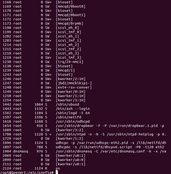
[그림 4.15] 동작 중인 MACCHIATObin 보드 - ps 명령 실행 모습

이상으로 MACCHIATObin 보드에 OpenWrt 17.10을 올리고, 간단히 network 동작 테스트를 진행해 보았다. 


5. MACCHIATObin 보드의 Ethernet Device Driver 분석
이 장의 내용은 [참고문헌 4]에서 영감을 받아 작성하였다.


[그림 5.1] Ethernet Link Layer 개념도 [출처: 참고문헌 4]


5.1) MACCHIATObin의 네트워크 인터페이스 
아래 그림은 MACCHIATObin 보드의 Ethernet 구성 요소를 전체적으로 보여주고 있다.

[그림 5.2] MACCHIATObin 보드 MAC/PHY 구성도 [출처: 참고문헌 4]

📌 SFP는 small form-factor pluggable transceiver를 뜻한다. SFP는 주로 광 케이블을 연결할 때 많이 사용되지만, copper cable을 연결하는 용도로도 사용될 수 있다.

먼저 eth2(그림 4.11 기준 가장 왼쪽, 위의 그림 5.2 기준 가장 아래쪽) 1G interface는 아래와 같이 가장 일반적인 MAC(PPv2.2)과 PHY(88E1512) 연결 형태로 구성되어 있다.

[그림 5.3] MACCHIATObin 보드 eth2 1G Interface [출처: 참고문헌 4]

다음으로 eth0, eth1 10G interface(그림 4.11 기준 가운데 두쌍 - SFP+ and Copper -)는 다음과 같이 MAC(PPv2.2)와 PHY(88X3310) 연결 형태로 구성되어 있다. SFP+의 경우는 내부에 i2c device가 포함되어 있어 i2c controller(SoC 내부)와 연결되어 있다(SFP+에 대한 레지스터 설정은 i2c를 통해 이루어짐).

[그림 5.4] MACCHIATObin 보드 eth0/1 10G Interface [출처: 참고문헌 4]

마지막으로 eth3(그림 4.11 기준 맨 우측 포트)은 2.5G interface를 지원하며, 중간에 별도의 PHY를 거치지 않고 곧바로 MAC(PPv2.2)과 연결되어 있다(즉, MAC to MAC 통신을 한다는 뜻). 경우에 따라서는 SFP+ 내에 PHY가 있는 경우도 있는데, 이 경우는 일반적인 MAC to PHY 통신으로 이어지게 된다.

[그림 5.5] MACCHIATObin 보드 eth3 2.5G MAC to MAC Interface [출처: 참고문헌 4]

5.2)  MACCHIATObin의 Ethernet Device Driver 분석
이런, 4.2~4.3 절에서 설치한 linux kernel(4.4.52)에는 [참고문헌 4]에서 말하는 kernel code가 보이질 않는다. 이 내용은 오히려 1장에서 설치한 linux kernel(4.19.62)에 보인다.

<device tree>
arch/arm64/boot/dts/marvell/armada-8040-mcbin.dts
<TBD>

[그림 5.6] armada-8040-mcbin.dts 내용 중 일부 발췌

<device drivers>
<Ethernet MAC controller>
drivers/net/ethernet/marvell/mvpp2/*
drivers/net/ethernet/marvell/mvmdio.c

<PHY driver>
drivers/net/phy/marvell.c
drivers/net/phy/marvell10g.c
<TBD>

Device Tree 및 device driver(ethernet MAC & PHY 관련)에 대한 분석은 추후 다시 하기로 하자.

<여기서 잠깐 !>
    => MUSDK와 ODP를 이용한 고속 패킷 처리 방법에 관하여 ...

Marvell User-Space SDK(a.k.a MUSDK)와 ODP(Open Data Plane)를 사용하면 고속 패킷 처리(linux kernel을 경유한 slow path가 아니라 PPv2.2를 이용한 fastpath)가 가능하다고 한다. 이 내용 자체도 하나의 커다른 주제가 될 듯한데, 자세한 사항은 아래 site를 참고하도록 하자.


[그림 5.7] MUSDK를 이용하여 PPv2 활용하기


[그림 5.8] ODP를 이용하여 PPv2 활용하기

이 장의 내용은 (아쉬움이 많이 남는 관계로) 추후 시간을 내어 좀 더 상세히 분석해 보아야 할 것 같다. 😂


6. 응용편: MACCHIATObin 보드를 SoftEther VPN Gateway로 만들기
이 장에서는 MACCHIATObin 보드를 VPN Gateway(SoftEther VPN 기반)로 만드는 과정을 소개하고자 한다. SoftEther VPN과 관련해서는 아래 blog post를 통해 이미 한 차례 소개한 바 있다.


위의 내용을 보면 알겠지만, SoftEther VPN을 cross-compile하는 과정은 연관 library가 많은 관계로 생각처럼 간단하지가 않다. x86_64 환경 처럼 arm64 개발 환경이 준비되어 있다면, cross-compile 없이 native compile 과정만으로도 원하는 결과를 얻을 수 있을텐데, 주변에서 arm64를 기반으로한 PC를 구하는 것은 매우 어렵다. 그렇다면 어떻게 해야 할까 ? 
📌 (비용은 좀 들겠지만) arm64를 지원하는 AWS EC2(or Google Cloud, Azure)를 활용하는 것도 하나의 방법이 될 수는 있다.

지금부터는 이 물음에 대한 대답으로, docker와 QEMU의 도움을 받아 x86 환경에서 arm64 개발 환경을 꾸미고, 그 위에서 SoftEther VPN을 build하는 방법을 소개하고자 한다. 물론 build가 성공한 후에는 target board 상에 올려 정상 동작하는지를 직접 확인해 볼 생각이다.


[그림 6.1] x86 위에 ARM emulation 환경 구축 [출처 - 참고문헌 10]

📌 물론 PINE64, ESPRESSObin 등 arm64 보드를 준비하고 그 위에서 직접 compile하는 방법도 하나의 대안이 될 수 있다. 하지만, 필요할 때마나 개발 보드를 하나씩 준비할 수는 없는 노릇이다.

6.1)  arm64v8(ubuntu 16.04)에서 SoftEther VPN build하기
지금부터는 arm64 emulation 환경을 만들고, 그 위에서 SoftEther VPN를 build해 보도록 하자.

<x86_64 Desktop PC>
$ sudo apt-get install qemu binfmt-support qemu-user-static
  => qemu, binfmt 등을 설치한다.
$ docker run --rm --privileged multiarch/qemu-user-static --reset -p yes
  => multi architecture를 지원하는 qemu container를 실행하자.
Unable to find image 'multiarch/qemu-user-static:latest' locally
latest: Pulling from multiarch/qemu-user-static
61c5ed1cbdf8: Pull complete 
6957fb4d1698: Pull complete 
ed8a5179ae11: Pull complete 
1ec39da9c97d: Pull complete 
2901bd4ab058: Pull complete 
Digest: sha256:28ebe2e48220ae8fd5d04bb2c847293b24d7fbfad84f0b970246e0a4efd48ad6
Status: Downloaded newer image for multiarch/qemu-user-static:latest
Setting /usr/bin/qemu-alpha-static as binfmt interpreter for alpha
Setting /usr/bin/qemu-arm-static as binfmt interpreter for arm
Setting /usr/bin/qemu-armeb-static as binfmt interpreter for armeb
Setting /usr/bin/qemu-sparc-static as binfmt interpreter for sparc
Setting /usr/bin/qemu-sparc32plus-static as binfmt interpreter for sparc32plus
Setting /usr/bin/qemu-sparc64-static as binfmt interpreter for sparc64
Setting /usr/bin/qemu-ppc-static as binfmt interpreter for ppc
Setting /usr/bin/qemu-ppc64-static as binfmt interpreter for ppc64
Setting /usr/bin/qemu-ppc64le-static as binfmt interpreter for ppc64le
Setting /usr/bin/qemu-m68k-static as binfmt interpreter for m68k
Setting /usr/bin/qemu-mips-static as binfmt interpreter for mips
Setting /usr/bin/qemu-mipsel-static as binfmt interpreter for mipsel
Setting /usr/bin/qemu-mipsn32-static as binfmt interpreter for mipsn32
Setting /usr/bin/qemu-mipsn32el-static as binfmt interpreter for mipsn32el
Setting /usr/bin/qemu-mips64-static as binfmt interpreter for mips64
Setting /usr/bin/qemu-mips64el-static as binfmt interpreter for mips64el
Setting /usr/bin/qemu-sh4-static as binfmt interpreter for sh4
Setting /usr/bin/qemu-sh4eb-static as binfmt interpreter for sh4eb
Setting /usr/bin/qemu-s390x-static as binfmt interpreter for s390x
Setting /usr/bin/qemu-aarch64-static as binfmt interpreter for aarch64    <=== 이걸 지원한다 !
Setting /usr/bin/qemu-aarch64_be-static as binfmt interpreter for aarch64_be
Setting /usr/bin/qemu-hppa-static as binfmt interpreter for hppa
Setting /usr/bin/qemu-riscv32-static as binfmt interpreter for riscv32
Setting /usr/bin/qemu-riscv64-static as binfmt interpreter for riscv64
Setting /usr/bin/qemu-xtensa-static as binfmt interpreter for xtensa
Setting /usr/bin/qemu-xtensaeb-static as binfmt interpreter for xtensaeb
Setting /usr/bin/qemu-microblaze-static as binfmt interpreter for microblaze
Setting /usr/bin/qemu-microblazeel-static as binfmt interpreter for microblazeel
Setting /usr/bin/qemu-or1k-static as binfmt interpreter for or1k

$ docker run -i -t --name arm64 arm64v8/ubuntu:16.04 /bin/bash
  => arm64v8 용 ubuntu 16.04를 실행(container)하자.
root@b2940a44a2ca:/# uname -a
Linux 88ab315a52ad 5.4.0-47-generic #51~18.04.1-Ubuntu SMP Sat Sep 5 14:35:50 UTC 2020 aarch64 aarch64 aarch64 GNU/Linux
root@88ab315a52ad:/# cat /etc/issue
Ubuntu 16.04.7 LTS \n \l

root@b2940a44a2ca:/# apt-get update
root@b2940a44a2ca:/# apt -y install cmake gcc g++ libncurses5-dev libreadline-dev libssl-dev make zlib1g-dev
  => SoftEther VPN build에 필요한 몇가지 package를 설치한다. 추가로 필요한 패키지가 있다면, 적절히 설치해 주면 된다.

📌 예상대로 docker + QEMU 구조이다 보니, 전체적으로 느린 느낌이다.

<SoftEther VPN build>
  => SoftEther VPN s/w와 관련해서는 아래 site 내용을 참조하자.


root@b2940a44a2ca:/# mkdir ~/workspace; cd workspace
root@b2940a44a2ca:/# git clone https://github.com/SoftEtherVPN/SoftEtherVPN.git
root@b2940a44a2ca:/# cd SoftEtherVPN
root@b2940a44a2ca:/# git submodule init && git submodule update
root@b2940a44a2ca:/# ./configure
📌 SoftEther VPN build를 위해서는 cmake 3.7 이상이 필요한데, Ubuntu 16.04는 3.6.1을 사용하고 있어 update해 주었다(자세한 과정은 생략).

root@b2940a44a2ca:/# make -C build
root@b2940a44a2ca:/# make -C build install

[그림 6.2] softether vpn build 결과물

root@b2940a44a2ca:/# tar cvzf sebin.tar.gz /usr/local/lib/lib*.so /usr/local/libexec/softether/
 => build 결과물을 tar.gz 파일로 묶어 보자.
/usr/bin/tar: Removing leading `/' from member names
/usr/local/lib/libcedar.so
/usr/bin/tar: Removing leading `/' from hard link targets
/usr/local/lib/libmayaqua.so
/usr/local/libexec/softether/
/usr/local/libexec/softether/vpnclient/
/usr/local/libexec/softether/vpnclient/vpnclient
/usr/local/libexec/softether/vpnclient/hamcore.se2
/usr/local/libexec/softether/vpncmd/
/usr/local/libexec/softether/vpncmd/hamcore.se2
/usr/local/libexec/softether/vpncmd/vpncmd
/usr/local/libexec/softether/vpnserver/
/usr/local/libexec/softether/vpnserver/hamcore.se2
/usr/local/libexec/softether/vpnserver/vpnserver
/usr/local/libexec/softether/vpnbridge/
/usr/local/libexec/softether/vpnbridge/hamcore.se2
/usr/local/libexec/softether/vpnbridge/vpnbridge

SoftEther VPN에 대한 build가 이루어졌으니, 이제부터는 build 결과 파일을 target board에 올린 후, vpnserver를 구동시켜 볼 차례이다. 편의상 지금부터는 (4장에서 설치한) OpenWrt 대신 Ubuntu 16.04를 사용하도록 하겠다.
📌 물론 OpenWrt에서도 SoftEther VPN을 구동시킬 수 있다. 이와 관련해서는 아래 site 내용이 도움이 될 것 같다.

6.2)  MACCHIATObin 보드에 Ubuntu 16.04 설치 후, SoftEther VPN vpncmd 실행하기
Ubuntu 16.04 설치와 관련해서는 MACCHIATObin wiki page에 상세히 소개되어 있다. 따라서 아래 site의 내용을 반드시 읽어보기 바란다. 여기에서는 꼭 필요한 내용을 중심으로 간략히 정리하고 넘어가도록 하겠다.


<Desktop PC>
$ gunzip -c ./ubuntu-xenial-mcbin_u-boot_sd.img_.gz | sudo dd of=/dev/sdb
7577600+0 레코드 들어옴
7577600+0 레코드 나감
3879731200 bytes (3.9 GB, 3.6 GiB) copied, 1773.49 s, 2.2 MB/s
📌 시간이 매우 오래 걸릴 수 있으니 주의하기 바란다.

<Target board>
Marvell>> setenv bootmmc 'mmc dev 0; ext4load mmc 1:2 $kernel_addr $image_name;ext4load mmc 1:2 $fdt_addr $fdt_name;setenv bootargs $console root=/dev/mmcblk1p2 rw rootwait; booti $kernel_addr - $fdt_addr'
📌 부트로더의 몇가지 설정을 변경해 준다. 자세한 사항은 위의 wiki page를 참조하도록 하자.

[그림 6.3] Ubuntu 16.04 부팅 모습

Ubuntu 16.04.3 LTS localhost.localdomain ttyS0

localhost login: root

root@localhost:~# apt-get update
root@localhost:~# apt-get install libncurses5-dev
root@localhost:~# apt-get install libreadline-dev
root@localhost:~# apt-get install libssl-dev
root@localhost:~# apt-get install zlib1g-dev
📌 SoftEther VPN 실행을 위해 필요한 몇가지 library를 설치해 주자. 설치가 불가한 경우에는 위의 library 파일을 docker 환경(6.1 절)에서 가져올 수도 있겠다.

root@localhost:~# su - chyi
  => user chyi를 사전에 추가하였다.
chyi@localhost:~$ mkdir workspace; cd workspace

<Desktop PC>
chyi@mars:/var/lib/tftpboot$ scp sebin.tar.gz chyi@192.168.2.1:~/workspace
chyi@192.168.1.1's password: 
sebin.tar.gz                                                               100%   14MB  63.6MB/s   00:00

<Target board>
chyi@localhost:~/workspace$ tar xvzf sebin.tar.gz 
usr/local/lib/libcedar.so
usr/local/lib/libmayaqua.so
usr/local/libexec/softether/
usr/local/libexec/softether/vpnclient/
usr/local/libexec/softether/vpnclient/vpnclient
usr/local/libexec/softether/vpnclient/hamcore.se2
usr/local/libexec/softether/vpncmd/
usr/local/libexec/softether/vpncmd/hamcore.se2
usr/local/libexec/softether/vpncmd/vpncmd
usr/local/libexec/softether/vpnserver/
usr/local/libexec/softether/vpnserver/hamcore.se2
usr/local/libexec/softether/vpnserver/vpnserver
usr/local/libexec/softether/vpnbridge/
usr/local/libexec/softether/vpnbridge/hamcore.se2
usr/local/libexec/softether/vpnbridge/vpnbridge

chyi@localhost:~/workspace$ export LD_LIBRARY_PATH=/home/chyi/workspace/usr/local/lib:$LD_LIBRARY_PATH
chyi@localhost:~/workspace$ cd usr/local/libexec/softether/vpncmd
  => OK, vpncmd가 동작한다.

[그림 6.4] softether vpncmd 실행 모습

6.3)  SoftEther VPN 연결 시험하기
이 절에서는 MACCHATObin 보드에 VPN server를 설치하고, (인터넷 반대편에 있는) Windows10 PC에 VPN Client를 설치한 후, 이를 서로 연결하는 시험을 진행해 보도록 하겠다. 시험용 Testbed는 다음과 같다.

<Testbed>
PC(VPN Client) => LTE Router <=== Internet ===> KT AP <= Small AP(repeater mode) <= MACCHATObin(VPN Server) <= Linux PC

VPN server  구동에 앞서, MACCHIATObin을 gateway로 만들기 위해 kernel의 Netfilter 기능을 enable하는 작업을 먼저 진행해야 한다. 

Kernel code download & build 방법은 역시 아래 page에 잘 정리되어 있으니 이를 참조하도록 한다.


$ export PATH=/home/chyi/workspace/mcbin/toolchain/gcc-linaro-5.3.1-2016.05-x86_64_aarch64-linux-gnu/bin:$PATH

$ git clone https://github.com/MarvellEmbeddedProcessors/linux-marvell .
$ git checkout linux-4.4.52-armada-17.10
$ git branch
  linux-3.10.70-15t1
* linux-4.4.52-armada-17.10

$ export ARCH=arm64
$ export CROSS_COMPILE=aarch64-linux-gnu-
$ make mvebu_v8_lsp_defconfig
$ make menuconfig
  => Netfilter 관련 설정은 꽤나 다양하니, 내용을 일일히 살펴본 후 적절히 enable시켜 주도록 한다(상세 내용 생략).

[그림 6.5] Netfilter enable하기

$ make -j4

Kernel compile이 완료되었으니, arch/arm64/boot/Image 파일을 target board에 올린 후, 부팅을 시도해 보자.

<Target board>
root@localhost:~# echo 1 > /proc/sys/net/ipv4/ip_forward
root@localhost:~# iptables -t nat -A POSTROUTING -o eth2 -j MASQUERADE
  => 시스템 부팅 후에는 ip_forwarding을 1로 설정하고, masquerading NAT rule을 하나 추가해 준다.

[그림 6.6] iptables masquerading rule 설정

OK, 이 상태에서 정상적으로 인터넷 접속이 되는 것을 확인했다면, 이제 부터는 vpnserver & vpncmd 설정을 시작할 준비할 차례다.

<Target board>
# export LD_LIBRARY_PATH=/home/chyi/workspace/usr/local/lib:$LD_LIBRARY_PATH
# cd usr/local/libexec/softether/vpnserver/
#  ./vpnserver start

[그림 6.7] vpnserver 실행 모습

# cd ../vpncmd
# ./vpncmd
  => 여기서는 VPN Server admin password만을 설정하도록 한다. 나머지 복잡한 설정은 VPN Server manager를 통해 진행할 것이다.

[그림 6.8] vpncmd 실행 후 VPN Server admin password 지정 모습

다음으로 VPN Server Manager를 이용하여 VPN Server에 대한 상세 설정을 진행한다(자세한 설정 과정은 생략).
Windows 10 PC(VPN Server Manager) ==> MACCHIATObin board(LAN port)
📌  VPN Server Manager  & VPN Client Manager 상세 설정 방법은 아래 site에 자세히 정리해 두었으니, 이를 참조하도록 하자(같은 내용을 반복해서 설명하지는 않겠음^^).

VPN Server 설정이 끝난 후에는 아래와 같이 bridge 및 dhcp server 설정을 진행하도록 하자.

<Target board>
  => 먼저 bridge 설정을 해 준다. bridge 설정 대상은 eth0와 tap_vpn(VPN server 설정시 생성되는 tap 기반 interface)이다.
root@localhost:~# ifconfig eth0 0.0.0.0
root@localhost:~# brctl addbr br0
root@localhost:~# brctl addif br0 eth0
root@localhost:~# brctl addif br0 tap_vpn
   => 얘는 VPN Server Manager에서 설정해 주어야만 생성이 된다.
root@localhost:~# ifconfig br0 192.168.2.1 netmask 255.255.255.0 up
root@localhost:~# brctl show
bridge name     bridge id               STP enabled     interfaces
br0             8000.005182112200       no              eth0
                                                                             tap_vpn

다음으로 br0 interface(LAN interface)를 대상으로 dhcp server를 구동시켜 주어야 한다. 
📌  dhcp server가 없으면, vpn client가 vpn server에 연결한 후, ip 주소 & default gw 설정을 못하게 되어 vpn 연결이 완성되지 못하는 문제가 발생한다.

root@localhost:~# apt-get install isc-dhcp-server
root@localhost:~# vi /etc/dhcp/dhcpd.conf 
  => 기존 내용을 모두 지우고, 아래 정보를 입력하도록 한다.

[그림 6.9] /etc/dhcp/dhcpd.conf 수정 내용
root@localhost:~# vi /etc/default/isc-dhcp-server
  => 아래와 같이 br0 interface 정보를 추가한다.
...
INTERFACES="br0"
~
root@localhost:~# systemctl restart isc-dhcp-server
  => dhcp server를 재구동시킨다.

지금까지 설정한 내용(vi 편집 내용 제외)을 하나의 shell script로 정리해 보면 다음과 같다. 부팅시 이 파일이 실행되도록 만들어 주면 편리할 것이다.

[그림 6.10] MACCHIATObin network 설정 내용 정리

자, 모든 것(VPN Server 설정)이 준비되었으니, VPN Client(Windows 10)에서 VPN Client Manager를 통해 vpn 연결을 시도해 보기로 하자(VPN client manager 설정 화면에 대한 설명은 생략).

               Windows 10 PC(VPN Client Manager) => 인터넷 => MACCHIATObin board(WAN port)

VPN 연결이 성공한 후 ip  정보를 확인해 보니, 마치 VPN Gateway 내부에 위치한 것 처럼 ip: 192.168.2.101이고, default gateway: 192.168.2.1 임을 알 수 있다.

[그림 6.11] VPN 연결 후, VPN Client ip 주소 할당 내용 확인

C:\> ping www.google.co.kr
  => OK, ping도 정상이다.

C:\> ssh chyi@192.168.2.1
  => Target board로 ssh login도 가능하다.

[그림 6.12] VPN Client PC에서 VPN Server에 ssh login 모습 

📌  SoftEther VPN(a.k.a SSL VPN)은 Ethernet Frame을 통째로 tunnel에 넣어 전달하기 때문에, (VPN Client가 설치된 PC 입장에서 볼 때) 마치 긴 LAN cable을 VPN Gateway의 LAN port에 연결한 듯한 착각을 일으키게 하는 특징(장점)이 있다. 쉽게 말해 집에 있지만 사무실 망에 연결되어 있는 것과 동일한 효과를 내게 해준다.

끝으로 아래 그림은 VPN client PC에서 (VPN server를 경유하여) internet 접속(web browser)을 할 경우의 최대 CPU 사용량(max: 50% 육박)을 보여주고 있다. 50%는 최악의 상황인 듯 보이며, (편차가 있기는 하지만) 대략 20 ~ 30% 정도의 CPU 점유율을 보여준다(생각보다 좀 많이 먹는 느낌이다).

[그림 6.13] VPN Server의 CPU 점유율 

이상으로 MACCHIATObin 보드에 SoftEther VPN server를 올리고, VPN Client로 접속(Remote access)하는 시험을 해 보았다. 실험 결과, 성능 좋은 Intel CPU 보다는 못하지만, MACCHIATObin을 SoftEther VPN Gateway로 사용하지 못할 이유는 없어  보인다^^.

______________________________

지금까지 MACCHIATObin 보드를 가지고, 이런 저런 시험을 진행해 보았다. 제목에서 보듯이 이번 blog post의 원래 의도는 5장(Ethernet device driver 분석)을 상세히 소개하는 것이었으나, 내용 정리를 하다보니 docker와 SoftEther VPN(6장)에 관한 내용으로 설명이 편중된 느낌이다.

언제나 그렇듯 미흡한 부분은 추후 좀 더 보충할 것을 기약하며 이번 글을 마치도록 하겠다. 이 글이 어느 누군가에게 조금이라도 도움이 되었으면 하는 바램을 가져본다. 😋


7. References
[2] ESPRESSObin ULTRA- Quick Start Guide -Rev 03
[3] Ethernet switch support in the Linux kernel, Alexandre Belloni, Bootlin
[4] From the Ethernet MAC to the link partner, Maxime Chevallier, Antoine Ténart, Bootlin
[6] marvell-link-street-88E6341-product-brief.pdf
[7] http://wiki.macchiatobin.net/tiki-index.php?page=BSP+HowTo
[8] https://www.digitalocean.com/community/tutorials/how-to-install-and-use-docker-on-ubuntu-18-04
[9] http://pyrasis.com/Docker/Docker-HOWTO#ps
[10] https://www.stereolabs.com/docs/docker/building-arm-container-on-x86/


SlowBoot

2020년 9월 12일 토요일

ESPRESSObin Ultra 보드와 MACCHIATObin 보드의 Switch & Ethernet Device Driver 분석

이번 blog post 부터는 앞으로 몇차례에 걸쳐 Marvell chip을 사용하는 ESPRESSObin Ultra 보드와 MACCHIATObin 보드에 관한 이야기(네트워크 관련)를 해 보고자 한다. 😎  이번에 소개하는 보드는 본 blog의 취지(?)하고는 맞지 않게 좀 비싼 보드들이다. 🏂


목차
1. Docker 환경 설정
2. ESPRESSObin Ultra 보드 소개
3. ESPRESSObin Ultra 보드의 Switching Device Driver 분석
4. MACCHIATObin 보드 소개
5. MACCHIATObin 보드의 Ethernet Device Driver 분석
6. 응용편:  MACCHIATObin 보드를 SoftEther VPN Gateway로 만들기
7. References


1. Docker 환경 설정 🐋
본론에 들어가기에 앞서서, 이번 장에서는 docker를 기반으로 개발 환경을 꾸미는 과정을 먼저 소개해 보고자 한다. Docker는 개발 환경을 맞추기 어려운 경우(예: PC Ubuntu 18.04 64bit <=> 실제로 필요한 환경 Ubuntu 12.04 32bit)에 이를 효과적으로 해결하는데 도움을 준다. 물론 VMware나 VirtuaBox와 같은 가상 환경을 사용해도 좋지만, 성능 면에서 볼 때 docker가 보다 효과적이라 볼 수 있다. Build하는데만 반나절 이상 걸리는 project(예: Android, Yocto ...)를 상상해 보라 ... VirtualBox로 build 하던 도중 resource 부족 문제로 중단되어 버린 경험이 있는 개발자라면, docker가 대안이라는 것을 쉽게 알 수 있을 것이다.

[그림 1.1] Docker 아키텍쳐
[출처: https://www.iconspng.com/image/48298/docker-architecture]

Docker를 활용하는 방법에 관해서는 이미 (3년 전에) 한 차례 소개한 바가 있다.


1.1) Docker 설치
이 절에서 소개하는 내용은 (기본적으로) 아래 site 내용을 참고하였다.


          => docker 명령어 사용법을 아주 간결하게 설명해 주고 있다.  👍💯


<Desktop PC - ubuntu 18.04>
$ sudo apt update
  =>  먼저, package database를 update해 준다.

$ sudo apt install apt-transport-https ca-certificates curl software-properties-common
  => apt가 HTTPS를 사용하여 package를 설치하기 위해 필요한 몇가지 패키지를 설치한다.

$ curl -fsSL https://download.docker.com/linux/ubuntu/gpg | sudo apt-key add -
  => 공식 docker repository용 GPG key를 추가한다.

$ sudo add-apt-repository "deb [arch=amd64] https://download.docker.com/linux/ubuntu bionic stable"
  => APT source에 docker repository를 추가한다.

$ sudo apt update
  => docker repository가 추가되었으니, package database를 다시 한번 update한다.

$ apt-cache policy docker-ce
  => 설치할 docker 후보를 확인해 본다(이 과정은 반드시 필요한 과정은 아님).

$ sudo apt install docker-ce
  => 실제로 docker ce(community edition)를 설치한다.

$ sudo systemctl status docker
  => 설치 후, 아래와 같은 내용이 출력된다면 정상적으로 설치가 된 것이다.

● docker.service - Docker Application Container Engine
   Loaded: loaded (/lib/systemd/system/docker.service; enabled; vendor preset: enabled)
   Active: active (running) since Wed 2020-09-09 10:52:56 KST; 17s ago
     Docs: https://docs.docker.com
 Main PID: 22955 (dockerd)
    Tasks: 11
   CGroup: /system.slice/docker.service
           └─22955 /usr/bin/dockerd -H fd:// --containerd=/run/containerd/containerd.sock

 9월 09 10:52:56 mars dockerd[22955]: time="2020-09-09T10:52:56.135659400+09:00" level=warning msg="Your k
 9월 09 10:52:56 mars dockerd[22955]: time="2020-09-09T10:52:56.135663932+09:00" level=warning msg="Your k
 9월 09 10:52:56 mars dockerd[22955]: time="2020-09-09T10:52:56.135668335+09:00" level=warning msg="Your k
 9월 09 10:52:56 mars dockerd[22955]: time="2020-09-09T10:52:56.135766281+09:00" level=info msg="Loading c
 9월 09 10:52:56 mars dockerd[22955]: time="2020-09-09T10:52:56.352215690+09:00" level=info msg="Default b
 9월 09 10:52:56 mars dockerd[22955]: time="2020-09-09T10:52:56.387724446+09:00" level=info msg="Loading c
 9월 09 10:52:56 mars dockerd[22955]: time="2020-09-09T10:52:56.430656835+09:00" level=info msg="Docker da
 9월 09 10:52:56 mars dockerd[22955]: time="2020-09-09T10:52:56.430851347+09:00" level=info msg="Daemon ha
 9월 09 10:52:56 mars dockerd[22955]: time="2020-09-09T10:52:56.444891890+09:00" level=info msg="API liste
 9월 09 10:52:56 mars systemd[1]: Started Docker Application Container Engine.

$ ps aux|grep docker
  => docker를 설치하면 실제로 dockerd라는 daemon이 하나 구동되게 된다.
root     22955  0.3  1.0 976400 82544 ?        Ssl  10:52   0:00 /usr/bin/dockerd -H fd:// --containerd=/run/containerd/containerd.sock
chyi     23498  0.0  0.0  15720  1068 pts/1    S+   10:53   0:00 grep --color=auto docker

$ sudo usermod -aG docker chyi
  => sudo 없이 docker 명령을 바로 사용할 수 있도록 자신의 계정을 docker group에 추가해 주자.
$ su - chyi
  => 계정 전환을 하고 난 후에는 sudo 없이 docker 명령 실행 가능해짐.
  => 혹은 logout 후 다시 login하게 되면 sudo 없이 docker 명령 실행 가능해짐.

chyi@mars:~$ docker info
Client:
 Debug Mode: false

Server:
 Containers: 2
  Running: 0
  Paused: 0
  Stopped: 2
 Images: 1
 Server Version: 19.03.12
 Storage Driver: overlay2
  Backing Filesystem: extfs
  Supports d_type: true
  Native Overlay Diff: true
 Logging Driver: json-file
 Cgroup Driver: cgroupfs
 Plugins:
  Volume: local
  Network: bridge host ipvlan macvlan null overlay
  Log: awslogs fluentd gcplogs gelf journald json-file local logentries splunk syslog
 Swarm: inactive
 Runtimes: runc
 Default Runtime: runc
 Init Binary: docker-init
 containerd version: 7ad184331fa3e55e52b890ea95e65ba581ae3429
 runc version: dc9208a3303feef5b3839f4323d9beb36df0a9dd
 init version: fec3683
 Security Options:
  apparmor
  seccomp
   Profile: default
 Kernel Version: 5.4.0-45-generic
 Operating System: Ubuntu 18.04.2 LTS
 OSType: linux
 Architecture: x86_64
 CPUs: 4
 Total Memory: 7.673GiB
 Name: mars
 ID: E4YZ:D7CM:RT6Y:U673:ACHU:7C6C:2QTK:UVKV:ZZS2:KOUD:5EVW:LUZR
 Docker Root Dir: /var/lib/docker
 Debug Mode: false
 Registry: https://index.docker.io/v1/
 Labels:
 Experimental: false
 Insecure Registries:
  127.0.0.0/8
 Live Restore Enabled: false

WARNING: No swap limit support

1.2) Docker 상에 Ubuntu 18.04 설치
Docker가 설치되었으니, 이제부터는 실제 개발 환경(Ubuntu 18.04와 Ubuntu 16.04)를 꾸며 보도록 하겠다. 이 절에서는 우선 (ESPRESSObin Ultra 보드를 위해) Ubuntu 18.04 환경을 먼저 만들어 보도록 하겠다(MACCHIATOBin 보드를 위한 Ubuntu 16.04는 4장에서 설치한다).

$ cd ~/workspace
$ vi Dockerfile_ubuntu1804
  => 파일을 하나 열고 아래와 같은 내용을 입력하자.

[그림 1.2] Dockerfile_ubuntu1804 파일 내용

📌 ubuntu, centos, redis 등 OS나 program의 이름을 가진 이미지가 공식 이미지이다. 한편 ubuntu:18.04 처럼 뒤에 tag를 붙여 주면 해당 버젼을 내려 받게 된다. tag 자리에 latest를 적어 주면 최신 버젼을 받게 된다. 또한 32bit 버젼을 download 받고 싶다면 i386/ubuntu:12.04 이런 식으로 명시해 주면 된다.
📌 Dockerfile 대신 "docker pull ubuntu:18.04" 명령 수행 후, docker run 하여 필요한 package를 설치해도 된다.
📌 Dockerfile 작성 방법과 관련해서는 아래 site를 참조하기 바란다.

$ docker build -f Dockerfile_ubuntu1804 -t u1804 .
  => 앞서 작성한 Dockerfile을 토대로 docker image를 생성하도록 하자. 마지막의 '.' 을 빼먹으면 안된다.

[그림 1.3] Dockerfile_ubuntu1804 파일을 이용하여 docker image 생성 모습

$ docker images
  => 생성된 docker image를 출력해 보면 다음과 같다. 아래 내용 중 u1804가 새로 생성된 docker image이다.
  => ubuntu 18.04가 ubuntu 18.04 original image이다. 참고로, 아래 내용 중에는 이전에 설치한 몇가지 이미지가 함께 출력되고 있다.

[그림 1.4] 생성된 docker image

$ docker run -i -t --name esbin1804 u1804 /bin/bash
  => 새로 생성한 docker image를 실행(container라고 함)해 보도록 하자.

root@26de74ece3fd:/# uname -a
Linux 26de74ece3fd 5.4.0-45-generic #49~18.04.2-Ubuntu SMP Wed Aug 26 16:29:02 UTC 2020 x86_64 x86_64 x86_64 GNU/Linux

(Dockerfile에 누락된) 몇가지 package를 추가로 설치해 보도록 하자.

root@26de74ece3fd:/# apt-get install ssh
  => docker ubuntu 18.04에 ssh server를 설치한다.

root@26de74ece3fd:/# apt-get install vim
  => vim도 설치하자.

root@26de74ece3fd:/# vi /etc/ssh/sshd_config
  => ssh root login을 위해 아래 내용을 추가하자.
...
#PermitRootLogin prohibit-password
PermitRootLogin yes
...

root@26de74ece3fd:/# service ssh restart
  => ssh server를 재구동시키자.

root@26de74ece3fd:/# apt-get install net-tools
  => ifconfig 등의 명령을 위해 net-tools를  설치한다.

[그림 1.5] ifconfig 명령 실행 모습

root@26de74ece3fd:/# passwd
  => root password를 설정하자.
Enter new UNIX password: 
Retype new UNIX password: 
passwd: password updated successfully

_____________________
chyi@mars:~$ ssh root@172.17.0.2
  => 다른 terminal 창에서 ssh로 현재 동작 중인 docker container에 로긴해 본다.

[그림 1.6] ssh로 docker container에 로긴한 모습

_____________________
다시 docker container 창으로 돌아와서 ...

root@26de74ece3fd:/# adduser chyi
  => 사용자를 하나 추가하자.
Adding user `chyi' ...
Adding new group `chyi' (1000) ...
Adding new user `chyi' (1000) with group `chyi' ...
Creating home directory `/home/chyi' ...
Copying files from `/etc/skel' ...
Enter new UNIX password: 
Retype new UNIX password: 
passwd: password updated successfully
Changing the user information for chyi
Enter the new value, or press ENTER for the default
Full Name []: 
Room Number []: 
Work Phone []: 
Home Phone []: 
Other []: 
Is the information correct? [Y/n] y

📌 사용자 계정 추가 등의 과정도 Dockerfile에 넣어주면 편리하다.

root@26de74ece3fd:/# exit

마지막으로 docker container를 빠져 나온 후, docker container 상에서 변경한 내용(몇가지 패키지 추가 및 파일 수정)을 docker image에 저장하는 작업(commit)을 진행하도록 하자. 참고로, 이 과정을 빼먹을 경우,  docker run 명령 재 수행 시, 이전에 수정했던 내용이 모두 사라져 버리게 되니, 반드시 이 과정을 해 주어야 한다.

$ docker commit -a "chunghan <chunghan.yi@gmail.com>" -m "add some packages" esbin1804 u1804
sha256:026516e59f658743596643446bdb86a7312a0957755586d0eab8c25685e5019f

  ➔ 사용방법 : docker commit < 옵션 > < 컨테이너 이름 > < 이미지 이름 >:< 태그 >
  ➔ < 컨테이너 이름 >: 직전에 docker run -i -t --name esbin1804 u1804 /bin/bash 에서
지정한 name
  ➔ < 이미지 이름 >:< 태그 >   (참고: : <태그>는 생략 가능함)

$ docker rm esbin1804
  => (다시 run 하기 전에)이전 container의 이름을 지워주도록 하자. 만일 이 과정을 빼먹을 경우, 매번 새로운 이름을 작명(?)해야 하는 수고를 해 주어야 한다.
  => docker ps -a 명령으로 이전에 실행했거나 현재 동작 중인 docker container를 확인할 수 있다.

$ docker run -i -t --name esbin1804 u1804 /bin/bash
root@a62c173f2d74:/#
  => commit하기 전에 수행했던 내용이 그대로 보존되어 있으면 정상적으로 commit된 것이다.

[그림 1.7] run_u1804.sh script 예

1.3) Docker 관련 몇가지 Tips
Q1) Host OS와 docker container간에 파일을 복사하고자 한다면 ?
A1-1) docker cp 명령을 사용합니다.
    $ docker cp esbin1804:/home/chyi/test/bbb.txt .

A1-2) 공유 디렉토리를 이용합니다. docker run시 아래와 같이 -v <host OS 디렉토리>:<container 디렉토리>를 주게 되면, 두 디렉토리간에 파일이 공유되게 됩니다.
   $ docker run -i -t -v /var/lib/tftpboot:/data --name esbin1804 u1804 /bin/bash

Q2) Container에서 tcp 80번 port를 열고, host OS의 80번 port와 연결하려면 ?
A2) -p 80:80 option을 주어 실행하면 됩니다. http://<Host IP>:80 하면 container에 접속할 수 있습니다.
     $ docker run -i -t -p 80:80 -v /var/lib/tftpboot:/data --name esbin1804 u1804 /bin/bash

Q3) 현재 동작 중인 container와 현재까지 실행되고 있거나, 실행된 적이 있는 모든 container 목록을 보려면 ? 혹은 이들을 제거하려면 ?
A3) 
     $ docker ps              # 현재 동작 중인 container 출력
     $ docker ps -a         #  현재까지 실행되고 있거나, 실행된 적인 있는 모든 container 목록 출력

     $ ​ docker rm $(docker ps -a -q)          # 모든 container 정보 삭제
     $ ​ docker rmi $(docker images -q)    # 모든 image 제거
_________________________________________

이상으로 본격적인 내용 소개에 앞서서 docker를 활용한 개발 환경 구축 방법을 소개해 보았다. Docker ! 정말로 훌륭한 녀석(?)이다. 잘 활용하면 개발에 커다란 도움을 줄 것으로 확신한다.


2. ESPRESSObin Ultra보드 소개
ESPRESSObin 보드와 관련해서는 이전 blog post를 통해 한 차례 소개한 바가 있다. 오늘은 최근(2019년) 새롭게 등장한 ESPRESSObin Ultra 보드(이하 Ultra 보드로 칭하겠음)를 소개해 보고자 한다. 사실 7월말에 하나를 주문했는데, (9월인데) 아직도 도착을 안하고 있다 😠

2.1) Ultra 보드 소개

[그림 2.1] ESPRESSObin Ultra 보드 - Access Point style 구성 [출처: 참고문헌 2]


[그림 2.2] ESPRESSObin Ultra 보드 H/W Block도 [출처: 참고문헌 2]

📌 H/W Block도 우측 하단을 보면, Marvell 88E6341 switching chip이 RGMII interface를 통해 CPU에 연결되어 있음을 알 수 있다.


[그림 2.3] ESPRESSObin Ultra 보드 주요 스펙

2.2) Ultra 보드 개발 환경 설정
그럼, 먼저 Ultra board용 bootloader, kernel source를 내려 받아 build를 해 보도록 하겠다. 이 절에서 소개하는 내용은 아래 site의 내용을 기준으로 한 것이다. Home page에 정식으로 내용이 올라와 있지 않은 것으로 보아, 아직도 개발 중이던지 ... 뭔가 약간의 문제가 있는 듯 보인다.


$ docker run -i -t --name esbin1804 u1804 /bin/bash
root@d9419ee9c06e:/# su - chyi
  => 이후의 모든 작업은 root 말고 사용자 계정으로 진행해도록 하자.  

chyi@d9419ee9c06e:~$ cd ~; mkdir workspace; cd workspace

<repo로 source download하기>
chyi@d9419ee9c06e:~/workspace$ git config --global user.email "chunghan.yi@gmail.com"
chyi@d9419ee9c06e:~/workspace$ git config --global user.name "Chunghan Yi"
  => git을 사용하려면 반드시 이 과정을 거쳐야 한다. 이는 기본 중의 기본^^

chyi@d9419ee9c06e:~/workspace$ repo init -u https://github.com/globalscaletechnologies/manifest.git -b espressobin-ultra -m espressobin_ultra-1.0.0.xml

chyi@d9419ee9c06e:~/workspace$ repo sync
  => repo sync를 해야 비로소 source code download가 시작된다.

chyi@d9419ee9c06e:~/workspace$ ls -al

[그림 2.4] ESPRESSObin Ultra source code 목록

<arm64 linaro toolchain 설치하기>
chyi@d9419ee9c06e:~/workspace$ mkdir toolchain;cd toolchain/
chyi@d9419ee9c06e:~/workspace/toolchain$ wget https://releases.linaro.org/components/toolchain/binaries/7.3-2018.05/aarch64-linux-gnu/gcc-linaro-7.3.1-2018.05-x86_64_aarch64-linux-gnu.tar.xz
  => linaro toolchain을 내려 받는다.

chyi@d9419ee9c06e:~/workspace/toolchain$ tar -xvf ./gcc-linaro-7.3.1-2018.05-x86_64_aarch64-linux-gnu.tar.xz
  => 압축을 푼다.

<bootloader용 arm32 toolchain 설치하기>
root@d9419ee9c06e:~# apt-get install gcc-arm-linux-gnueabi
  => 근데, 이미 설치가 되어 있다.
Reading package lists... Done
Building dependency tree       
Reading state information... Done
gcc-arm-linux-gnueabi is already the newest version (4:7.4.0-1ubuntu2.3).
0 upgraded, 0 newly installed, 0 to remove and 5 not upgraded.

📌 얘가 진짜 필요한게 맞는지 잘 모르겠다. 이후 진행되는 것을 보면 u-boot이 arm64용으로 build가 되는 듯한데 ... 이 부분은 추후 재 확인을 해 보도록 하겠다.

<Compile 환경 설정하기>
$ vi ~/.bashrc
  => bashrc에 아래의 환경 설정 내용을 추가해 주자.
...
export PATH=/home/chyi/workspace/toolchain/gcc-linaro-7.3.1-2018.05-x86_64_aarch64-linux-gnu/bin:$PATH

# Set the cross compiler
export CROSS_COMPILE=/home/chyi/workspace/toolchain/gcc-linaro-7.3.1-2018.05-x86_64_aarch64-linux-gnu/bin/aarch64-linux-gnu-

# Set path for MV_DDR component
export MV_DDR_PATH=/home/chyi/workspace/mv_ddr_marvell

# Set U-Boot image path
export BL33=/home/chyi/workspace/u-boot-marvell/u-boot.bin

# Set WTP Tools path
export WTP=/home/chyi/workspace/a3700-utils-marvell
~

$ source ~/.bashrc
  => 위의서 설정한 환경 변수를 적용해 준다.

u-boot, kernel 등을 compile하기 전에 몇가지 package를 더 설치하자. 사실 아래 내용은 (build 과정에서 발견하여) 나중에 추가한 것이다.

root@d9419ee9c06e:~# apt-get install -y libncurses-dev
root@d9419ee9c06e:~# apt-get install -y bc


<u-boot build하기>
chyi@d9419ee9c06e:~/workspace$ make -C ./u-boot-marvell gti_ccpe-88f3720_defconfig
chyi@d9419ee9c06e:~/workspace$ make -C ./u-boot-marvell menuconfig
chyi@d9419ee9c06e:~/workspace$ make -C ./u-boot-marvell DEVICE_TREE=armada-3720-ccpe

<ATF build하기>
chyi@d9419ee9c06e:~/workspace$ make -C ./atf-marvell DEBUG=0 USE_COHERENT_MEM=0 LOG_LEVEL=20 CLOCKSPRESET=CPU_1000_DDR_800 PLAT=a3700 DDR_TOPOLOGY=5 all fip
📌 ATF는 ARM Trusted Firmware를 뜻한다.

<kernel build하기>
chyi@d9419ee9c06e:~/workspace$ make -C ./linux ARCH=arm64 gti_ccpe-88f3720_defconfig
chyi@d9419ee9c06e:~/workspace$ make -C ./linux ARCH=arm64 menuconfig
chyi@d9419ee9c06e:~/workspace$ make -C ./linux ARCH=arm64 -j4

<통합 이미지 생성하기>
오 ! 이런~ 전체 build(환경 설정 포함)를 해 주는 script가 이미 준비되어 있다. 얘를 이용하여 다시 build해 보자.

chyi@d9419ee9c06e:~/workspace$ source ./env-espressobin_ultra.sh
chyi@d9419ee9c06e:~/workspace$ gtibuild bootloader
chyi@d9419ee9c06e:~/workspace$ gtibuild kernel
chyi@d9419ee9c06e:~/workspace$ gtibuild all

[그림 2.5] ESPRESSObin Ultra build 결과물


<Target board에 설치하기>
<TBD> 
지금까지 build한 내용은 보드가 도착하면 시도해 보도록 하자. 참고로, (앞선 build 과정에서 보이지 않았던) rootfs는 prebuilt 형태로 제공된다.


__________________________
root@d9419ee9c06e:/# exit
$ docker commit -a "chunghan <chunghan.yi@gmail.com>" -m "add some packages" esbin1804 u1804
  => 지끔까지 작업한 내용을 docker image에 반드시 저장하자.


3. ESPRESSObin Ultra보드의 Switching Device Driver 분석
이 장의 내용은 [참고문헌 3]에서 영감을 받아 작성하였다.


3.1) Ultra 보드 Switch device 소개
ESPRESSObin Ultra 보드는 아래 그림과 같이 Marvell 88E6341 switching chip(Topaz Switch라고도 함)을 사용한다. 이 88E6341 switch는 왼쪽으로는 CPU랑 RGMII(data 통신용) 및 MDC/MDIO(제어용)로 연결되어 있으며, 오른쪽으로는 4개의 LAN port와 1개의 WAN port(얘는 다시 SGMII interface를 통해 88E1512 Gb PHY와 연결)와 연결되어 있다.


[그림 3.1] Marvell 88E6341 Ethernet Switch(1) [출처: 참고문헌 2]

아래 그림은 Marvell 88E6341 Ethernet Switch의 구성 요소를 간략히 보여주고 있다.

[그림 3.2] Marvell 88E6341 Ethernet Switch(2) [출처: 참고문헌 6]

한편, Linux kernel에는 위와 같은 switch device를 위한 framework(switchdev)이 이미 정의되어 있는데, 이와 관련해서는 아래 내용을 살펴볼 필요가 있다.

     1) Documentation/networking/switchdev.txt
     2) net/switchdev/switchdev.c
     3) include/net/switchdev.h

[그림 3.3] linux kernel switch device driver model

대개의 경우, CPU(정확하게는 MAC)와 switching chip은 PCIe 혹은 xMII 등의 interface를 통해 data를 주고 받으며, MDC/MDIO(= SMI) or SPI 등을 통해 control이 이루어지게 된다.

[그림 3.4] Ethernet Switch와 CPU의 관계도(개념도) [출처: 참고문헌 3]

그런데, Marvell은 위의 switchdev framework으로는 부족하다고 판단했는지, 자신들의 switch chip을 위해 DSA(Distributed Switch Architecture)라는 새로운 switch framework을 별도로 설계하였다. 이를 그림으로 그려보면 다음과 같은데, 이는 여러 개의 switching chip을 CPU에 붙이는 경우(cascade 구성)를 고려한 것으로, 처음에는 Marvell에서 만들었으나, 이후 다른 vendor들에서도 점차로 이 framework을 사용하는 추세인 듯 하다.

[그림 3.5] DSA(Distributed Switch Architecture) 개념도 [출처: 참고문헌 3]

3.2) Switch device driver 분석
이 절에서는 Marvell 88E6341 switching chip을 위한 device tree 및 driver(DSA driver)를 분석해 보도록 하겠다.

시작에 앞서 DSA의 개념을 보다 구체적으로 이해할 필요가 있겠는데, 이를 위해서는 아래 파일을 먼저 살펴 보아야 한다.

     1) Documentation/networking/dsa/dsa.txt
     2) Documentation/devicetree/bindings/net/dsa/dsa.txt
     3) Documentation/devicetree/bindings/net/dsa/marvell.txt
     4) Documentation/devicetree/bindings/net/ethernet.txt

다음으로 살펴볼 내용은 device tree이다.

armada-37xx.dtsi
|
v
armada-372x.dtsi
|
v
armada-3720-ccpe.dts

(긴 말할 것 없이) 이 중 맨 아래에 있는 dts 파일 즉, arch/arm64/boot/dts/marvell/armada-3720-ccpe.dts를 mdio node를 중심으로 분석해 보면 다음과 같다.
______________________________________________________________
&eth0 {     /* switch device를 cpu에 연결시켜 주는 device, 역시 앞서 정의되어 있는 eth0를 override하여 재 정의하고 있음 */
    pinctrl-names = "default";
    pinctrl-0 = <&rgmii_pins>;
    phy-mode = "rgmii-id";           /* switch와 연결되는 interface: RGMII */
    status = "okay";

    fixed-link {
        speed = <1000>;
        full-duplex;
    };
};

&mdio {     /* DSA에서는 이런 구문이 여러개 존재할 수 있음, &mdio는 앞서 정의된 mdio를 override하여 재 정의하는 것을 뜻함.  */
    status = "okay";

    extphy: ethernet-phy@0 {
        reg = <1>;
    };

    switch0: switch0@1 {      /* switching chip을 기술해 주는 부분 */
        compatible = "marvell,mv88e6085";     /* 이걸로 driver 검색 */
        #address-cells = <1>;
        #size-cells = <0>;       
        reg = <3>;

        dsa,member = <0 0>;      /* cluster 0, switch 0을 의미 */

        ports {      /* switch에 붙어 있는 ports를 기술해 주는 부분 */
            #address-cells = <1>;
            #size-cells = <0>;

            switch0port0: port@0 {
                reg = <0>;
                label = "cpu";       /* 0번 port를 cpu port로  사용 */
                ethernet = <&eth0>;      /* cpu port의 경우는 ethernet property를 추가해 줌 */
            };

            switch0port1: port@1 {
                reg = <1>;
                label = "lan0";
                phy-handle = <&switch0phy1>;             /* (A) */
            };

            switch0port2: port@2 {
                reg = <2>;
                label = "lan1";
                phy-handle = <&switch0phy2>;
            };

            switch0port3: port@3 {
                reg = <3>;
                label = "lan2";
                phy-handle = <&switch0phy3>;
            };

            switch0port4: port@4 {
                reg = <4>;
                label = "lan3";
                phy-handle = <&switch0phy4>;
            };

            switch0port5: port@5 {
                reg = <5>;
                label = "wan";
                phy-handle = <&extphy>;
                phy-mode = "sgmii";       /* wan port는 SGMII interface를 통해 외부 phy와 연결되어 있음 */
            };
        };

        mdio {   /* 이름이 앞서와 겹쳐서 헷갈릴 수 있는데, 여기서의 mdio는 mdio-bus를 의미함 - 여기서의 이름은 크게 중요치 않음. */
            #address-cells = <1>;
            #size-cells = <0>;

            switch0phy1: switch0phy1@11 {     /* (A) */
                reg = <0x11>;     /* mdc/mdio로 연결되는 PHY는 i2c 장치 처럼 주소를 갖는다 */
            };
            switch0phy2: switch0phy2@12 {
                reg = <0x12>;
            };
            switch0phy3: switch0phy3@13 {
                reg = <0x13>;
            };
            switch0phy4: switch0phy4@14 {
                reg = <0x14>;
            };
        };
    };
};
______________________________________________________________

이번에 살펴 볼 부분은 device driver 쪽이다. device driver를 분석할 때는 (전체를 이해하는게 어려울 수 있으니) 초기화 코드(init, probe 등)와 사용자와의 interface(sysfs, read/write/ioctl, netlink socket 등)를 중심으로 살펴볼 필요가 있다.

Source 위치는 아래와 같이 grep으로 찾을 수 있다.
$ grep -rl "marvell,mv88e6085" *
linux/drivers/net/dsa/mv88e6xxx/chip.c

DSA driver의 전체 구조를 파악하는 것은 생각 만큼 간단하지가 않다. [참고 문헌 5]는 DSA의 전체 구조는 물론이고, switchdev, swconfig 등 기존에 구현되어 있는 switch 관련 framework을 전반적으로 소개해 주고 있어, 여기에 소개한다.

[그림 3.6]  DSA Architecture(1) [출처: 참고문헌 5]

[그림 3.7]  DSA Architecture(2) [출처: 참고문헌 5]

[그림 3.8]  DSA Switch Tags 처리(1) [출처: 참고문헌 5]

[그림 3.9]  DSA Switch Tags 처리(2) [출처: 참고문헌 5]

이상의 내용을 기초로 하여 코드를 분석해 보아야 하는데, 지면 관계상, 여기에서는 chip.c 파일의 초기화 부분과 probe 함수 내용을 capture하는 것으로 코드 분석을 대신하고자 한다. 👻

[그림 3.10] Marvell mv88e6xxx driver 초기화 코드(1)

[그림 3.11] Marvell mv88e6xxx driver 초기화 코드(2) - probe 함수


<여기서 잠깐 !>
Ultra 보드에는 4MB 크기의 SPI NOR flash가 한개 장착되어 있다. 아래 내용은 이와 관련한 device tree 내용을 capture한 것으로, NOR flash 내에 3개의 파티션 즉, u-boot, hw-info, u-boot-env이 위치하고 있음을 알 수 있다. 이는 값비싼 SPI NOR flash에는 자주 변경하지 않으면서 크기가 작은 u-boot만을 넣어 두고, 용량이 큰 linux kernel과 rootfs는 값싼 eMMC에 배치하는 전형적인 구성이라고 볼 수 있다.

[그림 3.12] SPI NOR flash에 대한 device tree 표현

📌 SPI flash는 SPI interface를 통해 CPU와 연결된다. SPI는 CS(Chip Select), SCK(Serial Clock), MOSI(Master Output Slave Input), MISO(Master Input Slave Output)라는 4가닥 선을 사용하는 serial 통신 방식이다. 요즘은 이 방식을 많이 사용한다.
____________________________

<여기서 잠깐 !>
최근에 출시된 802.11ax(WiFi 6)를 지원하는 보드(SoC: Qualcomm IPQ6010)가 있어 여기에 소개해 본다.


[그림 3.13] WiFi 6(802.11ax)를 지원하는 보드 - DR6018 v2
____________________________


늘 느끼는 거지만 (요즘 한층 더 복잡해진) linux device driver를 분석하는 것은 결코 만만한 일이 아니다. 특히 device 별로 새로운 framework이 소개되고 있는 탓에 이해를 더 어렵게 만들고 있는 것 같다.

시작할 때 의도했던 것과는 다르게 분석 내용이 너무 수준 이하(?)라는게 좀 아쉽다. 부족한 부분은 추후 좀 더 보충해 볼 것을 기약하며 이번 장을 마치도록 하겠다. 😅


To be continued ... 


7. References
[2] ESPRESSObin ULTRA- Quick Start Guide -Rev 03
[3] Ethernet switch support in the Linux kernel, Alexandre Belloni, Bootlin
[4] From the Ethernet MAC to the link partner, Maxime Chevallier, Antoine Ténart, Bootlin
[6] marvell-link-street-88E6341-product-brief.pdf
[7] http://wiki.macchiatobin.net/tiki-index.php?page=BSP+HowTo
[8] https://www.digitalocean.com/community/tutorials/how-to-install-and-use-docker-on-ubuntu-18-04
[9] http://pyrasis.com/Docker/Docker-HOWTO#ps


SlowBoot