2016년 12월 17일 토요일

Connecting the GPS Click board to Atmel SAMA5D3 Xplained board

In this blog, I'll introduce how to integrate the GPS Click board to Atmel SAMA5D3 Xplained board. To connect the GPS Click board to SAMA5D3 Xplained board, mikroBUS connector(Arduino UNO shield) is needed additionally.
Figure 0.1 GPS Click Board by MikroElektronika

 Figure 0.2 mikroBUS Arduino UNO shield

<Contents>
1. Introduction to GPS Click board and mikroBUS connector
2. Device drivers for UART
3. How to run the GSP application


1. Introduction to GPS Click board and mikroBUS connector
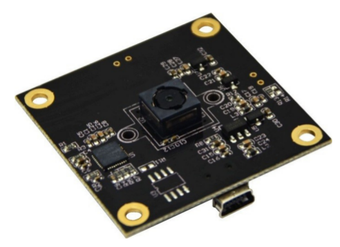
1.1 GPS L10 Click board
GPS click carries the LEA-6S high performance positioning engine from u-bloxGPS click is designed to run on a 3.3V power supply and communicate with the target MCU through UART or I2C interface. Data can also be acquired through a PC application using the onboard USB port. The click has an onboard connector that is compatible with both active and passive antennas.
GPS click can simultaneously track up to 16 satellites while searching for new ones. The LEA-6S module’s TTFF (time to fist fix) is less than one second — this is the measure of time necessary for a GPS receiver to get satellite signals and navigation data, and based on this information, calculate a position (a fix)
  • LEA-6 u-blox module
    • Navigate down to –162 dBm and –148 dBm coldstart
    • Power consumption in power save mode: 36mW
    • TTFF less than 1 second in Hot Start
    • Horizontal position accuracy 2.5m
  • UART and I2C interface
  • USB connector
  • 3.3V power supply
Figure 1.1 GPS Click with ublox module

Figure 1.2 GPS Click schematic with ublox engine

1.2 mikroBUS Form Factor
The MIKROE-1581 Arduino Uno click shield is an extension for Arduino Uno and any other Arduino compatible board. It's a simple shield with two mikroBUS host sockets that allow user to connect more than 75 different types of click boards to the Arduino. Quickly add functionalities like GSM, GPS, Wi-Fi, ZigBee, Bluetooth, or thunder detection, proximity and colour sensing and so on.
  • Two mikroBUS host connectors for attaching click boards
  • Arduino compatible connector on the opposite side
  • Shield is designed to stay within dimensions of Arduino Uno for smoother integration
  • Brings click board connectivity to a wide range of Arduino compatible boards

Figure 1.3 Pinout for mikroBUS Arduino UNO shield


Figure 1.4 Schematic for GPS click Board and mikroBUS Arduino UNO shield

Connecting the GPS Click board to the SAMA5D3 XPlained board requires using the Arduino UNO click shield adapter board(Figure 0.2). The adapter board makes the following connections:

<Table 1.1 Pin map for three boards>


2. Device drivers for UART
The GPS click board connects to the host platform via the mikroBUS connector. Communications with the GPS click, both configuration input and GPS message output, are by a simple asynchronous serial (UART) connection. By default, the serial port connection configuration between the SAMA5D3 Xplained and GPS click is 9600 bps, 8 bits by word, no parity, 1 stop bit, no hardware flow control. Data are "logic level" voltages (0V, 3.3V) and not RS-232 levels (-12V, +12V). The GPS click module requires a GPS antenna for proper operation.

In this chapter, an analysis for both UART device tree and device driver codes will be done.

2.1 Device Tree for UART
At first, let's check the device tree codes for PC29(UART RX0) and PC30(UART TX0) pins on SAMA5D3 Xplained board.

Code 2.1 pinctrl node for PIOC 29 and 30 in sama5d3.dtsi

Code 2.2 uart0 node in sama5d3.dtsi

Code 2.3 serial5 alias for uart0 in sama5d3.dtsi


Code 2.4 uart0 node in at91-sama5d3_xplained_pda4.dts

2.2 Device driver for UART
You can easily find the following uart device driver file with "atmel,at91sam9260-usart" compatible string which is mentioned int the sama5d3.dtsi file(See the Code 2.2).

drivers/tty/serial/atmel_serial.c

==============================================================
static int atmel_serial_probe(struct platform_device *pdev)
{
    struct atmel_uart_port *atmel_port;
    struct device_node *np = pdev->dev.of_node;
    struct atmel_uart_data *pdata = dev_get_platdata(&pdev->dev);
    void *data;
    int ret = -ENODEV;
    bool rs485_enabled;

    BUILD_BUG_ON(ATMEL_SERIAL_RINGSIZE & (ATMEL_SERIAL_RINGSIZE - 1));

    if (np)
        ret = of_alias_get_id(np, "serial");
    else
        if (pdata)
            ret = pdata->num;

    if (ret < 0)
        /* port id not found in platform data nor device-tree aliases:
         * auto-enumerate it */
        ret = find_first_zero_bit(atmel_ports_in_use, ATMEL_MAX_UART);

    if (ret >= ATMEL_MAX_UART) {
        ret = -ENODEV;
        goto err;
    }

    if (test_and_set_bit(ret, atmel_ports_in_use)) {
        /* port already in use */
        ret = -EBUSY;
        goto err;
    }

    atmel_port = &atmel_ports[ret];
    atmel_port->backup_imr = 0;
    atmel_port->uart.line = ret;
    atmel_serial_probe_fifos(atmel_port, pdev);

    atomic_set(&atmel_port->tasklet_shutdown, 0);
    spin_lock_init(&atmel_port->lock_suspended);

    ret = atmel_init_port(atmel_port, pdev);
    if (ret)
        goto err_clear_bit;

    atmel_port->gpios = mctrl_gpio_init(&atmel_port->uart, 0);
    if (IS_ERR(atmel_port->gpios)) {
        ret = PTR_ERR(atmel_port->gpios);
        goto err_clear_bit;
    }

    if (!atmel_use_pdc_rx(&atmel_port->uart)) {
        ret = -ENOMEM;
        data = kmalloc(sizeof(struct atmel_uart_char)
                * ATMEL_SERIAL_RINGSIZE, GFP_KERNEL);
        if (!data)
            goto err_alloc_ring;
        atmel_port->rx_ring.buf = data;
    }

    rs485_enabled = atmel_port->uart.rs485.flags & SER_RS485_ENABLED;

    ret = uart_add_one_port(&atmel_uart, &atmel_port->uart);
    if (ret)
        goto err_add_port;

#ifdef CONFIG_SERIAL_ATMEL_CONSOLE
    if (atmel_is_console_port(&atmel_port->uart)
            && ATMEL_CONSOLE_DEVICE->flags & CON_ENABLED) {
        /*
         * The serial core enabled the clock for us, so undo
         * the clk_prepare_enable() in atmel_console_setup()
         */
        clk_disable_unprepare(atmel_port->clk);
    }
#endif

    device_init_wakeup(&pdev->dev, 1);
    platform_set_drvdata(pdev, atmel_port);
    /*
     * The peripheral clock has been disabled by atmel_init_port():
     * enable it before accessing I/O registers
     */
    clk_prepare_enable(atmel_port->clk);

    if (rs485_enabled) {
        atmel_uart_writel(&atmel_port->uart, ATMEL_US_MR,
                  ATMEL_US_USMODE_NORMAL);
        atmel_uart_writel(&atmel_port->uart, ATMEL_US_CR,
                  ATMEL_US_RTSEN);
    }

    /*
     * Get port name of usart or uart
     */
    atmel_get_ip_name(&atmel_port->uart);

    /*
     * The peripheral clock can now safely be disabled till the port
     * is used
     */
    clk_disable_unprepare(atmel_port->clk);

    return 0;

err_add_port:
    kfree(atmel_port->rx_ring.buf);
    atmel_port->rx_ring.buf = NULL;
err_alloc_ring:
    if (!atmel_is_console_port(&atmel_port->uart)) {
        clk_put(atmel_port->clk);
        atmel_port->clk = NULL;
    }
err_clear_bit:
    clear_bit(atmel_port->uart.line, atmel_ports_in_use);
err:
    return ret;
}
==============================================================

Actually any modification to device tree and device drivers for UART is not required because they are already prepared to work well. So, let's connect the GPS Click board to SAMA5D3 Xplained board carefully.

Figure 2.1 View to which GPS Click, mikroBUS and SAMA5D3 Xplained are integrated


3. How to run the GPS application
Now, we need a GPS application to run, so let's download a sample code from the following site.
https://www.element14.com/community/docs/DOC-69753/l/gps-click-l10-accessory-board

The code flow of this sample program is as follows.

Figure 3.1 The code flow of gps sample application

From now on, I'll summarize the steps to build this gps application under the BuildRoot environment.

<Directory for original source codes>
chyi@earth:~/Atmel/demo/GPS/gps_app$ ls -la
합계 36
drwxrwxr-x 2 chyi chyi  4096 12월 16 15:55 .
drwxrwxr-x 5 chyi chyi  4096 12월 16 15:50 ..
-rw-rw-r-- 1 chyi chyi   161 12월 16 15:55 Makefile
-rw-rw-r-- 1 chyi chyi 20772 12월 16 15:50 sam_gps_click.c
==============================================================

<BuildRoot Directory> $ cd ~/Atmel/buildroot/package
$ mkdir gps_app
$ cd gps_app

$ vi Config.in
Code 3.1 Config.in for gps application(package)

vi gps_app.mk
Code 3.2 gps_app.mk for gps application(package)

$ cd ..

vi Config.in
...
menu "Miscellaneous"
    source "package/aespipe/Config.in"
    source "package/bc/Config.in"
    source "package/clamav/Config.in"
    source "package/collectd/Config.in"
    source "package/domoticz/Config.in"
    source "package/empty/Config.in"
    source "package/gnuradio/Config.in"
    source "package/googlefontdirectory/Config.in"
    source "package/gr-osmosdr/Config.in"
    source "package/gsettings-desktop-schemas/Config.in"
    source "package/haveged/Config.in"
#test code - added by chunghan.yi@gmail.com - 12/16/2016
    source "package/gps_app/Config.in"
#-- --
    source "package/mcrypt/Config.in"
    source "package/mobile-broadband-provider-info/Config.in"
    source "package/qemu/Config.in"
    source "package/qpdf/Config.in"
    source "package/shared-mime-info/Config.in"
    source "package/snowball-init/Config.in"
    source "package/taskd/Config.in"
    source "package/wine/Config.in"
    source "package/xutil_util-macros/Config.in"
endmenu
...


$ cd ..
make menuconfig
Figure 3.2 buildroot menuconfig to select gps_app

make

or
$ make gps-app-rebuild

<Output> chyi@earth:~/Atmel/buildroot/output/build/gps_app-0.0.1$ ls -la
합계 512
drwxr-xr-x   2 chyi chyi   4096 12월 16 15:56 .
drwxr-xr-x 118 chyi chyi   4096 12월 16 15:56 ..
-rw-r--r--   1 chyi chyi 236701 12월 16 15:56 .br_filelist_after
-rw-r--r--   1 chyi chyi 236642 12월 16 15:56 .br_filelist_before
-rw-r--r--   1 chyi chyi      0 12월 16 15:56 .stamp_built
-rw-r--r--   1 chyi chyi      0 12월 16 15:56 .stamp_configured
-rw-r--r--   1 chyi chyi      0 12월 16 15:56 .stamp_rsynced
-rw-r--r--   1 chyi chyi      0 12월 16 15:56 .stamp_target_installed
-rw-r--r--   1 chyi chyi    161 12월 16 15:55 Makefile
-rwxr-xr-x   1 chyi chyi   9364 12월 16 15:56 sam_gps_click
-rw-r--r--   1 chyi chyi  20772 12월 16 15:50 sam_gps_click.c
==============================================================

OK, build is complete until now. Let's try NFS booting with this binary and run this application as follows.

<After rebooting>
sam_gps_click
  => But, this application does not print any message on the console.

Simply, this program opens the /dev/ttyS5 port with 9600, 8N1 attributes and sends the following GPS command to the same port.
$PMTK314,1,1,0,0,0,0,0,0,0,0,0,0,0,0,0,0,0,0,0*00
And then it waits to read some data from the /dev/ttyS5 port, but any data doesn't arrive. I have no GPS antenna now(actually I've attached an available Wi-Fi antenna instead). Is this truly a cause for this abnormal result ?

Oops, power was the true reason to this issue. I didn't connect 3.3V power between mikroBUS and SAMA5D3 Xplained board because I couldn't find a suitable male header in GPS Click product package. So I decided to use USB power for GPS click board like Figure 3.3. OK,the green LED for GPS click board is turned on.


Figure 3.3 USB power for GPS click board

Finally, the output of gps application starts to be printed to the console(Figure 3.4). But it seems that the correct output is not showed yet. Why ?

Figure 3.4 Output message from gps application

Hmm...
I rechecked the gps sample application codes and found that this code is not made for ublox gps module but Quectel gps module.

Now there are three things to do:
1) To read ublox GPS protocol specifications and rewrite gps application codes.
2) Soldering for GPS click board
  In figure 3.3, I used white Scotch tape to fix GPS click board on mikroBUS.
3) To purchase a GPS antenna


References
1. GPS_Click_QSG_103014.pdf - element 14
2. gps-click-l10-manual-v100.pdf - MikroElektronika
3. mikrobus-standard-specification-v200.pdf - MikroElektronika
4. http://docs.mikroe.com/GPS_click
5. LEA-6_DataSheet_(GPS.G6-HW-09004).pdf - ublox
6. u-blox6_ReceiverDescriptionProtocolSpec_(GPS.G6_SW-10018).pdf - ublox


Slowboot


2016년 12월 15일 목요일

How to connect an USB Camera with SAMA5D3 Xplained board

LCD 장치와 함께 USB Camera도 하나 구입했다. 당초 계획은 ISI(Image Sensor Interface)에 맞는 CMOS-type image 센서가 장착된 camera를 구매하는 거였으나, 이게 여유치가 않았다. 이번 blog에서는 지난 blog(LCD)에 이어, USB camera를 Atmel SAMA5D3 Xplained board에 연결시켜 보고, 그 과정에서 device driver(device tree) 관련하여 issue가 될 만한 부분을 살펴 보고자 한다. USB camera 라서 특별히 device tree를 수정할 사항이 없는 것이 좀 아쉽지만 말이다...
<목차>
1. CAM8200-U Camera 소개
2. Device Driver 관련 작업(under BuildRoot environment)
3. Camera 동작 시험(under BuildRoot environment)


1. CAM8200-U Camera 소개
CAM8200-U는 Embest Technology에서 디자인한 5 메가 픽셀 USB camera 모듈로 automatic focus, white balance, exposure control 및 gain control을 지원한다. 상세 스펙을 소개해 보면 다음과 같다.


아래 그림 1.1은 CAM8200-U의 USB 인터페이스를 보여주고 있다.

그림 1.1 CAM8200-U의 USB OTG 인터페이스 (출처 - 참고 문헌 [1])


2. Device Driver 관련 작업
이번 절에서는 USB Camera가 동작 가능하도록 kernel config를 조정해 보도록 하자.

2.1 kernel config 조정
$ cd buildroot
$ make linux-menuconfig

<Multimedia USB Adapter USB Video Class 지정>
    Device Drivers --->
          <*>   Multimedia support --->
                [*]   Media USB Adapters  --->
               <*>   USB Video Class (UVC)
               [*]     UVC input events device support (NEW)


그림 2.1 kernel menuconfig - USB Video Class 지정 화면

<Graphics Framebuffer Console support>
    Device Drivers --->
           Graphics support  --->
          Console display driver support  --->
         <*> Framebuffer Console support
          -*-   Map the console to the primary display device


그림 2.2 kernel menuconfig - framebuffer conosole 지원 지정 화면

참고로, 참고 문헌 [1]에 언급된 kernel configuration 내용이 좀 old version을 기준으로 되어 있는 듯 보인다.

2.2 kernel 재 build 및 NAND booting
  => buildroot 전체를 build할 필요 없이, kernel만 재 build하도록 하자.
==============================================================
chyi@earth:~/Atmel/buildroot$ make linux-rebuild
rm -f /home/chyi/Atmel/buildroot/output/build/linux-linux4sam_5.5/.stamp_staging_installed
rm -f /home/chyi/Atmel/buildroot/output/build/linux-linux4sam_5.5/.stamp_target_installed
rm -f /home/chyi/Atmel/buildroot/output/build/linux-linux4sam_5.5/.stamp_images_installed
rm -f /home/chyi/Atmel/buildroot/output/build/linux-linux4sam_5.5/.stamp_host_installed
rm -f /home/chyi/Atmel/buildroot/output/build/linux-linux4sam_5.5/.stamp_built
>>> linux linux4sam_5.5 Building
PATH="/home/chyi/Atmel/buildroot/output/host/bin:/home/chyi/Atmel/buildroot/output/host/sbin:/home/chyi/Atmel/buildroot/output/host/usr/bin:/home/chyi/Atmel/buildroot/output/host/usr/sbin:/home/chyi/bin:/home/chyi/.local/bin:/usr/local/sbin:/usr/local/bin:/usr/sbin:/usr/bin:/sbin:/bin:/usr/games:/usr/local/games:/snap/bin" BR_BINARIES_DIR=/home/chyi/Atmel/buildroot/output/images /usr/bin/make -j5 HOSTCC="/usr/bin/gcc" HOSTCFLAGS="" ARCH=arm INSTALL_MOD_PATH=/home/chyi/Atmel/buildroot/output/target CROSS_COMPILE="/home/chyi/Atmel/buildroot/output/host/usr/bin/arm-buildroot-linux-gnueabihf-" DEPMOD=/home/chyi/Atmel/buildroot/output/host/sbin/depmod INSTALL_MOD_STRIP=1 -C /home/chyi/Atmel/buildroot/output/build/linux-linux4sam_5.5 zImage
  CHK     include/config/kernel.release
  CHK     include/generated/uapi/linux/version.h
  CHK     include/generated/utsrelease.h
make[3]: 'include/generated/mach-types.h'은(는) 이미 업데이트되었습니다.
  CHK     include/generated/timeconst.h
  CHK     include/generated/bounds.h
  CHK     include/generated/asm-offsets.h
  CALL    scripts/checksyscalls.sh
  CHK     include/generated/compile.h
  Kernel: arch/arm/boot/Image is ready
  Kernel: arch/arm/boot/Image is ready
  Kernel: arch/arm/boot/zImage is ready
  CHK     include/config/kernel.release
  CHK     include/generated/uapi/linux/version.h
  CHK     include/generated/utsrelease.h
make[3]: 'include/generated/mach-types.h'은(는) 이미 업데이트되었습니다.
  CHK     include/generated/timeconst.h
  CHK     include/generated/bounds.h
  CHK     include/generated/asm-offsets.h
  CALL    scripts/checksyscalls.sh
  Building modules, stage 2.
  MODPOST 42 modules
PATH="/home/chyi/Atmel/buildroot/output/host/bin:/home/chyi/Atmel/buildroot/output/host/sbin:/home/chyi/Atmel/buildroot/output/host/usr/bin:/home/chyi/Atmel/buildroot/output/host/usr/sbin:/home/chyi/bin:/home/chyi/.local/bin:/usr/local/sbin:/usr/local/bin:/usr/sbin:/usr/bin:/sbin:/bin:/usr/games:/usr/local/games:/snap/bin" BR_BINARIES_DIR=/home/chyi/Atmel/buildroot/output/images /usr/bin/make -j5 HOSTCC="/usr/bin/gcc" HOSTCFLAGS="" ARCH=arm INSTALL_MOD_PATH=/home/chyi/Atmel/buildroot/output/target CROSS_COMPILE="/home/chyi/Atmel/buildroot/output/host/usr/bin/arm-buildroot-linux-gnueabihf-" DEPMOD=/home/chyi/Atmel/buildroot/output/host/sbin/depmod INSTALL_MOD_STRIP=1 -C /home/chyi/Atmel/buildroot/output/build/linux-linux4sam_5.5 at91-sama5d3_xplained_pda4.dtb
make[3]: 'arch/arm/boot/dts/at91-sama5d3_xplained_pda4.dtb'은(는) 이미 업데이트되었습니다.
>>> linux linux4sam_5.5 Installing to target
# Install modules and remove symbolic links pointing to build
# directories, not relevant on the target
  INSTALL crypto/af_alg.ko
  INSTALL crypto/algif_hash.ko
  INSTALL crypto/algif_skcipher.ko
  INSTALL crypto/echainiv.ko
  INSTALL drivers/leds/leds-blinkm.ko
  INSTALL drivers/leds/leds-regulator.ko
  INSTALL drivers/media/i2c/soc_camera/ov2640.ko
  INSTALL drivers/media/i2c/soc_camera/ov5642.ko
  INSTALL drivers/media/i2c/soc_camera/ov6650.ko
  INSTALL drivers/media/i2c/soc_camera/ov772x.ko
  INSTALL drivers/media/i2c/soc_camera/ov7740.ko
  INSTALL drivers/media/i2c/soc_camera/ov9640.ko
  INSTALL drivers/media/i2c/soc_camera/ov9740.ko
  INSTALL drivers/media/usb/gspca/gspca_main.ko
  INSTALL drivers/mtd/ubi/gluebi.ko
  INSTALL drivers/net/wireless/libertas_tf/libertas_tf.ko
  INSTALL drivers/net/wireless/libertas_tf/libertas_tf_usb.ko
  INSTALL drivers/net/wireless/mwifiex/mwifiex.ko
  INSTALL drivers/net/wireless/mwifiex/mwifiex_sdio.ko
  INSTALL drivers/net/wireless/mwifiex/mwifiex_usb.ko
  INSTALL drivers/net/wireless/rt2x00/rt2500usb.ko
  INSTALL drivers/net/wireless/rt2x00/rt2800lib.ko
  INSTALL drivers/net/wireless/rt2x00/rt2800usb.ko
  INSTALL drivers/net/wireless/rt2x00/rt2x00lib.ko
  INSTALL drivers/net/wireless/rt2x00/rt2x00usb.ko
  INSTALL drivers/net/wireless/rt2x00/rt73usb.ko
  INSTALL drivers/spi/spidev.ko
  INSTALL drivers/staging/wilc1000/wilc1000-sdio.ko
  INSTALL drivers/staging/wilc1000/wilc1000.ko
  INSTALL drivers/usb/gadget/function/u_serial.ko
  INSTALL drivers/usb/gadget/function/usb_f_acm.ko
  INSTALL drivers/usb/gadget/function/usb_f_mass_storage.ko
  INSTALL drivers/usb/gadget/function/usb_f_obex.ko
  INSTALL drivers/usb/gadget/function/usb_f_serial.ko
  INSTALL drivers/usb/gadget/function/usb_f_ss_lb.ko
  INSTALL drivers/usb/gadget/legacy/g_mass_storage.ko
  INSTALL drivers/usb/gadget/legacy/g_serial.ko
  INSTALL drivers/usb/gadget/legacy/g_zero.ko
  INSTALL drivers/usb/gadget/libcomposite.ko
  INSTALL drivers/usb/gadget/udc/atmel_usba_udc.ko
  INSTALL lib/crc-ccitt.ko
  INSTALL lib/crc-itu-t.ko
  DEPMOD  4.4.26-linux4sam_5.5
# Installing dtc (device tree compiler) as host tool, if selected
if grep -q "CONFIG_DTC=y" /home/chyi/Atmel/buildroot/output/build/linux-linux4sam_5.5/.config; then /usr/bin/install -D -m 0755 /home/chyi/Atmel/buildroot/output/build/linux-linux4sam_5.5/scripts/dtc/dtc /home/chyi/Atmel/buildroot/output/host/usr/bin/linux-dtc ; if [ ! -e /home/chyi/Atmel/buildroot/output/host/usr/bin/dtc ]; then ln -sf linux-dtc /home/chyi/Atmel/buildroot/output/host/usr/bin/dtc ; fi fi
>>> linux linux4sam_5.5 Installing to images directory
/usr/bin/install -m 0644 -D /home/chyi/Atmel/buildroot/output/build/linux-linux4sam_5.5/arch/arm/boot/zImage /home/chyi/Atmel/buildroot/output/images/zImage
# dtbs moved from arch/<ARCH>/boot to arch/<ARCH>/boot/dts since 3.8-rc1
cp /home/chyi/Atmel/buildroot/output/build/linux-linux4sam_5.5/arch/arm/boot/dts/at91-sama5d3_xplained_pda4.dtb /home/chyi/Atmel/buildroot/output/images
==============================================================

Build 결과물(zImage, dtb file)을 /tftpboot 디렉토리로 복사하자.

chyi@earth:~/Atmel/buildroot/output/build/linux-linux4sam_5.5/arch/arm/boot$ cp zImage /tftpboot/

chyi@earth:~/Atmel/buildroot/output/build/linux-linux4sam_5.5/arch/arm/boot/dts$ cp ./at91-sama5d3_xplained_pda4.dtb /tftpboot/
==============================================================

Target board의 NAND flash에 zImage와 dtb file을 올리자.

<Target board u-boot 명령>
=> tftp 0x21000000 zImage
gmac0: PHY present at 7
gmac0: Starting autonegotiation...
gmac0: Autonegotiation complete
gmac0: link up, 100Mbps full-duplex (lpa: 0x45e1)
Using gmac0 device
TFTP from server 192.168.1.100; our IP address is 192.168.1.50
Filename 'zImage'.
Load address: 0x21000000
Loading: ################################################################# #################################################################
################################
3 MiB/s
done
Bytes transferred = 3824160 (3a5a20 hex)
=> nand erase 0x200000 0x600000

NAND erase: device 0 offset 0x200000, size 0x600000
Erasing at 0x7e0000 -- 100% complete.
OK
=> nand write 0x21000000 0x200000 0x3a5a20

NAND write: device 0 offset 0x200000, size 0x3a5a20
 3824160 bytes written: OK
=> 
==============================================================

3. Camera 동작 시험
자, 이제 USB camera를 SAMA5D3 Xpalined board에 연결한 후, 2절에서 새로 build한 zImage로 부팅을 시도해 보자.

3.1 USB camera  정상 인식 확인
아래 내용으로 보아서는 일단 USB camera가 정상적으로 인식된 듯 보인다. 실제로 camera가 제대로 동작하는지를 확인하기 위해서 V4L2 interface를 사용하는 camera application이 하나 필요하다.

그림 3.1 USB camera 인식 내용 확인 - kernel booting message

그림 3.2 USB camera 인식 내용 확인 - sysfs 내용

3.2 camera application test
아래 site에서 간단한 camera application program을 하나 download 받자.

(*) source code를 보니, Common Display Framework을 설계한 Laurent Pinchart (laurent.pinchart@skynet.be)가 작성한 코드이다.

$ mkdir CAM8200-U
$ unzip ./CAM8200-U.zip

이 program을 돌리려면, cross-compile이 필요한데, 편의상 이전 blog에서 설명했던 buildroot 환경에서 작업을 하도록 하자.

<방법 1 - BuildRoot 외부에서 build한 후, rootfs에 binary만 포함 시키는 방법>
export PATH=/home/chyi/Atmel/buildroot/output/host/usr/bin:$PATH
  => BuildRoot의 toolchain path를 잡는다.

$ vi Makefile
  => luvc_test(camera test app)의 Makefile을 수정한다.

코드 3.1 camera application을 위한 Makefile

$ make clean
$ make
$ ls -l
-rw-rw-r-- 1 chyi chyi   238 12월 14 21:00 Makefile
-rw-rw-r-- 1 chyi chyi    65 12월 14 18:53 README.chyi
-rw-rw-r-- 1 chyi chyi   837  4월 20  2015 README.txt
-rwxrwxr-x 1 chyi chyi 18224 12월 14 21:00 luvc_test
-rw-rw-r-- 1 chyi chyi 21931  4월 20  2015 luvc_test.c

$ cp ./luvc_test /home/chyi/Atmel/buildroot/output/images/rootfs/sbin
  => luvc_test app을 rootfs 디렉토리로 복사한다.

<방법 2 - BuildRoot에 패키지 형태로 추가하기>
$ cd ~/Atmel/demo/camera/camera_app
$ ls -l
-rw-rw-r-- 1 chyi chyi   269 12월 15 12:09 Makefile
-rw-rw-r-- 1 chyi chyi   837 12월 15 12:05 README.txt
-rw-rw-r-- 1 chyi chyi 21931 12월 15 12:05 luvc_test.c
$ vi Makefile
코드 3.2 원본 Makefile for luvc_test
====================================================

$ cd ~/Atmel/buildroot/package
$ mkdir camera_app
$ cd camera_app
$ vi Config.in
코드 3.3 Config.in for camera_app

$ vi camera_app.mk
코드 3.4 camera_app.mk

$ cd ..
$ vi Config.in
  => 아래 한 줄을 추가한다.
...
menu "Miscellaneous"
    source "package/aespipe/Config.in"
    source "package/bc/Config.in"
    source "package/clamav/Config.in"
    source "package/collectd/Config.in"
    source "package/domoticz/Config.in"
    source "package/empty/Config.in"
    source "package/gnuradio/Config.in"
    source "package/googlefontdirectory/Config.in"
    source "package/gr-osmosdr/Config.in"
    source "package/gsettings-desktop-schemas/Config.in"
    source "package/haveged/Config.in"
#test code - added by chunghan.yi@gmail.com - 12/15/2016
    source "package/camera_app/Config.in"
#-- --
    source "package/mcrypt/Config.in"
    source "package/mobile-broadband-provider-info/Config.in"
    source "package/qemu/Config.in"
    source "package/qpdf/Config.in"
    source "package/shared-mime-info/Config.in"
    source "package/snowball-init/Config.in"
    source "package/taskd/Config.in"
    source "package/wine/Config.in"
    source "package/xutil_util-macros/Config.in"
endmenu

$ cd ..
$ make menuconfig
  => camera_app을 선택한다.

그림 3.3 camera_app package 메뉴 선택 화면

$ make

$ cd ~/Atmel/buildroot/output/build/camera_app-0.0.1$ ls -l
합계 48
-rw-r--r-- 1 chyi chyi   269 12월 15 12:09 Makefile
-rw-r--r-- 1 chyi chyi   837 12월 15 12:05 README.txt
-rwxr-xr-x 1 chyi chyi 15644 12월 15 12:15 luvc_test
-rw-r--r-- 1 chyi chyi 21931 12월 15 12:05 luvc_test.c
====================================================

이상의 두가지 방법 중, 하나를 이용하여 생성한 luvc_test를 가지고, NFS booting을 시도한 후, 아래 명령을 실행해 보자.

$ /sbin/luvc_test
   => 명령이 실행되는 걸 보니, 제대로 cross-compile이 되었다.


그림 3.2 luvc_test 명령 실행 결과 화면

다음으로, 아래와 같은 option을 주어 사진(still shot)을 찍어 보도록 하자.

luvc_test -c -f mjpg -s 320x240 -c --skip 10 /dev/video0
  => camera가 capture한 내용이 /tmp/capture.jpg파일 형태로 저장된다.
  => 10개의 frame을 skip하고 (안정적인 상태의) cut을  찍음.
  => jpg 파일을 scp 명령으로 Host PC로 가져와 확인해 보니, 아래 그림 3.3과 같이 제대로 나온다(USB camera 동작에는 이상이 없다는 뜻).


그림 3.3 Camera로 찍은 사진 - 오늘 마신 *벅스 커피

다음으로 아래와 같은 option을 주어, camera가 capture한 내용을 LCD로 출력해 보자.

$ luvc_test -c -f mjpg -s 320x240 -S /dev/video0
  => camera로 capture한 내용을 LCD로 연속해 출력한다.

이 명령의 경우는 camera에 찍힌 내용이 실시간으로 LCD 화면에 출력되기는 한다. 하지만, 화면의 내용이 실물을 알아보기 매우 어려울 정도로 깨져보인다. 왜일까 ?


내일은 luvc_test source 및 Atmel hlcdc driver code(drivers/gpu/drm/atmel-hlcdc/atmel_hlcdc_dc.c)를 살펴 보도록 해야 겠다.

지금까지 간략하게 나마 USB camera를 SAMA5D3 Xplained board에 장착하는 과정을 blog에 담아 보았다. 역시 설명이 부족하거나, 추가 시험이 필요한 부분은 추후 좀 더 보강해 보도록 하자.


References
1. Cam8200_QGS_03132015.pdf - element14
2. CAM8200-U User Manual.pdf - Embest Technology


Slowboot

2016년 12월 14일 수요일

How to connect a TFT-LCD to Atmel SAMA5D3 Xplained board

Atmel SAMA5D3 Xplained board에 연결할 TFT-LCD와 connector가 도착했다. 이번 blog에서는 TFT-LCD 장치를 SAMA5D3 Xplained board에 연결하는 과정을 소개하고자 한다. 특히 구매한 제품에 포함된 touch screen controller 장치가 SPI 인터페이스를 사용하는 관계로, 관련 device driver(device tree)를 어떻게 수정하는지에 관해 알아볼 것이며, 또한 LCD 장치와 관련한 device tree & driver 내용도 함께 분석해 보기로 하겠다.
<목차>
1. LCD8000-43T-EX(LCD Connector) 소개
2. Device Tree 및 Device Driver 수정하기 
3. LCD Driver Review


1. LCD8000-43T-EX(LCD Connector) 소개
LCD8000-43T-EX(그림 1.1, 이하 LCD-EX로 표기)는 4.3 inch TFT-LCD 디스플레이 장치(그림 1.2)를 위한 16/24-bit RGB parallel conversion 모듈(쉽게 말해 connector)이다.

 그림 1.1 LCD8000-43T-EX 모듈(flat ribon cable 장착)

그림 1.2 4.3  인치 TFT-LCD Display(flat ribon cable 장착)

LCD-EX 모듈을 좀 더 상세히 살펴보면, 아래 그림 1.3과 같은데, LCD-EX 모듈 안에는 TSC2046 touch screen controller chip과 AM51117 3.3V regulator가 올라가 있으며, 주변 장치들과의 상호 연결을 위한 여러 개의 확장 핀(J1, J2, J11 ~ J15)이 장착되어 있음을 알 수 있다(실제로는 뒷면에 J13 확장 핀도 있으나 여기서는 사용하지 않으므로 생략).


그림 1.3 LCD-EX 주요 PIN(J1: TFT-LCD, J2: SAMA5D3 연결)(출처 - 참고문헌 [1])

그럼, 먼저 여러 확장 핀의 용도를 살펴 본 후, 주요 device 관련 내용을 확인해 보도록 하겠다.

먼저 J1 확장 핀은 TFT-LCD 쪽에 연결되는 핀으로, 아래 테이블에 의하면 50개의 pin으로 구성되어 있음을 알 수 있다. 반면 J2 확장 핀은 MPU(SAMA5D3 Xplained) 쪽으로 연결되는 부분으로 24 pin으로 구성되어 있다. J1, J2 각 pin에 대한 설명은 참고 문헌 [1]에 잘 나와 있으니 이를 참고하기 바란다.

표 1.1 LCD-EX의 J pin 내용 설명(출처 - 참고문헌 [1])

또한, 좌측의 J11/J12/J14/J15 확장 핀(Jumper Cap)은 SPI 연결과 관련이 있는 듯 보이는데, SAMA5D3 Xplained board의 revision(A or B)에 따라 다르게 연결되어야만  한다. 현재 가지고 있는 SAMA5D3 Xplained board의 version이 A에 해당하므로, J11/J12/J14/J15 jumper cap을  아래 표를 기준으로 조정(모두 PIN2/PIN3가 연결되도록 조정)해 주어야 한다.

표 1.2 LCD-EX의 SPI  Line Module 선택 관련(출처 - 참고문헌 [1])

지금까지 확장 핀의 용도에 대해 알아 보았으니, 다음으로 TSC2046 touch screen controller와 AM51117 regulator chip에 대해 알아 보기로 하자.

다음 그림 1.4는 LCD-EX에 장착되어 있는 TSC2046 touch screen controller(실제로 SPI slave 장치)의 인터페이스를 자세히 보여준다. 우선 TSC2046 chip 우측의 DCLK(Serial Conversion Clock), CS(Chip Select), DIN(Serial Data In), DOUT(Serial Data Out) 4개의 pin이 SAMA5D3 Xplained와의 SPI 연결을 위해 사용된다. 또한 TSC2046 좌측의 X+, Y+, X-, Y- 등은 Touch screen으로 부터의 입력(아날로그 data)을 받는 부분으로 볼 수 있다.

그림 1.4 TSC2046 touch screen controller 인터페이스(출처 - 참고문헌 [2])

그림 1.5는 TSC2046의 H/W 블록도를 보여준다. 참고로, TSC2046은 ADS7846(4-wire touch screen controller)의 개선(upgrade) 버젼으로써 ADS7846과는 100% pin-compatible한 특징을 갖고 있다(ADS7846을 언급하는 이유는 이미 관련 device driver가 linux에 구현되어 있고, 본 blog에서는 이를 사용할 계획이기 때문임).

그림 1.5 TSC2046 touch controller 블록도(출처 - 참고문헌 [2])


여기서 잠깐 !
SPI에 관한 사항을 이해하기 위해서는 이전 blog의 내용을 확인해 보기 바란다.


다음으로, 아래 그림 1.6은 TPS51117 synchronous step-down controller의 블록도이다. LCD-EX 상에는 AM51117 chip이 붙어 있는 것으로 보이나, 관련 정보를 검색해 본 결과, 인터넷 상에서는 TPS51117 정보가 보이는 것으로 보아 아마도 동일 chip이 아닌가 싶다(아닐 수도 있음 :(). 이 칩과 관련해서는 특별히 programming해야 할 부분이 일단 없어 보이기(?) 때문에, H/W 블록도 하나만 남기고, 추가 설명은 건너 띄기로 하자(좀 찜찜한데 :(). 자세한 내용은 참고 문헌 [3]을 참조해 보기 바란다.


그림 1.6 TPS51117 synchronous buck controller 블록도(출처 - 참고문헌 [3])

주의) 제품 소개서에 따르면 AM51117이 3.3V regulation chip이며, I2C control 및 PWM backlight control도 한다고 되어 있는데, 아무래도 이에 관한 내용도 추후 확인해 보아야 하겠다.

마지막으로 SAMA5D3 Xplained 보드(아래 그림 좌측 Controller A5) 및 TFT-LCD(아래 그림 우측)를 연결해 주는 LCD-EX의 인터페이스에 대한 블록도(그림 1.7)를 정리해 보는 것으로 이절을 마무리하고자 한다.

그림 1.7 LCD-EX 주요 인터페이스(MPU와 LCD 간 연결)(출처 - 참고문헌 [1])

여기서 잠깐 !
이번 절에서는 정작 제일 중요한 LCD 장치에 관한 설명을 빼 먹었다. 구매한 제품 site에서 관련 정보를 찾아 보았으나, 불행히도 관련 datasheet가 없다. 대신에, 아래 site에 LCD에 관한 동작 원리가 쉽게 설명되어 있으니, 참조해 보기 바란다.


2. Device Tree 및 Device Driver 수정하기 
Ribon cable을 target board와 LCD-EX에 상호 연결하고, LCD 화면이 어찌 출력되는지 확인해 보았다.

와우 ! 그 결과, 아래 그림 처럼 LCD 화면에 UI(아마도 Qt로 만든 듯 보임)가 출력되었다.
근데, touch가 안 먹힌다... ???

그림 2.1 LCD 화면에 UI 화면 출력

주의) Ribon cable을 반대로 연결할 경우, LCD에 불(backlight)도 안켜지고, 아무런 동작이 안될 것이니, 주의해야 한다.


그림 2.2 부팅 후, ps 명령 실행 결과 화면

앞서 1절에서 LCD-EX 보드의 기본적인 구성을 확인해 보았으니, (touch 문제를 해결하기 위해)이제는 이를 kernel과 device tree에 적절히 반영하는 작업을 진행해 보기로 하자.

2.1 Device Tree 수정 작업
Touch가 제대로 동작하기 위해서는 device tree 내용 수정이 필요해 보이는데, 우선 이번 project에 맞는 device tree로는 아래 파일을 이용하기로 한다.
arch/arm/boot/dts/at91-sama5d3_xplained_pda4.dts

================================
sama5d3.dtsi
^
|
sama5d36.dtsi
at91-sama5d3_xplained_dm_pda4.dtsi
^
|
at91-sama5d3_xplained_pda4.dts
================================

SAMA5D3 Xplained board 관련 device tree에 대해서는 이전 blog에 어느 정도 설명이 되어 있으니, 이를 참고하기로 하고, 바로 본론으로 들어가 보도록 하자.

먼저 at91-sama5d3_xplained_pda4.dts 파일에 TSC2046 touch device(SPI slave device)를 위한 내용을 아래 코드 2.1과 같이 추가해 보자.
아래 내용을 보면, spi slave 장치명으로 tsc2046이 아니라, ads7846을 추가했음을 알 수 있는데, 이는 이미 1절에서 설명한 바와 같이 ads7846이 tsc2046과 100% pin compatible이며, kernel에 ads7846 관련 driver가 구현되어 있기 때문에 이를 활용하기 위한 차원에서 그렇게 한 것이다.

 코드 2.1 at91-sama5d3_xplained_pda4.dts 파일 수정 내용 - spi slave 장치 추가

다음으로 atmel에서 기본으로 제공하는 atmel_mxt_ts 장치(i2c touch screen 장치)를 사용할 필요가 없으므로, interrupt 설정 부분을 막도록 한다. 이 부분은 tsc2046에서 그대로 사용할 것이다.

코드 2.2 at91-sama5d3_xplained_dm_pda4.dtsi 파일 수정 내용>

2.2 kernel menuconfig 수정
다음으로 kernel menuconfig를 통해 TSC2046(input device, touch screen controller)를 enable 시키도록 하자.

                         Device Drivers --->
                                  Input device support --->
                                           Touchscreens  --->
                                                 <*>   ADS7846/TSC2046/AD7873 and AD(S)7843 based touchscreens
                                                 <>   Atmel mXT I2C Touchscreen

그림 2.3 TSC2046 touch screen driver 선택 화면

여기서 잠깐 !
TSC2046 device driver 코드는 아래 파일에 구현되어 있으니, 독자 여러분께서 직접 관련 코드를 분석해 보시기 바란다.

drivers/input/touchscreen/ads7846.c

<ads7846 driver probe 함수 내용 발췌>
==============================================================
static int ads7846_probe(struct spi_device *spi)
{
    const struct ads7846_platform_data *pdata;
    struct ads7846 *ts;
    struct ads7846_packet *packet;
    struct input_dev *input_dev;
    unsigned long irq_flags;
    int err;

    if (!spi->irq) {
        dev_dbg(&spi->dev, "no IRQ?\n");
        return -EINVAL;
    }

    /* don't exceed max specified sample rate */
    if (spi->max_speed_hz > (125000 * SAMPLE_BITS)) {
        dev_err(&spi->dev, "f(sample) %d KHz?\n",
                (spi->max_speed_hz/SAMPLE_BITS)/1000);
        return -EINVAL;
    }

    /*
     * We'd set TX word size 8 bits and RX word size to 13 bits ... except
     * that even if the hardware can do that, the SPI controller driver
     * may not.  So we stick to very-portable 8 bit words, both RX and TX.
     */
    spi->bits_per_word = 8;
    spi->mode = SPI_MODE_0;
    err = spi_setup(spi);
    if (err < 0)
        return err;

    ts = kzalloc(sizeof(struct ads7846), GFP_KERNEL);
    packet = kzalloc(sizeof(struct ads7846_packet), GFP_KERNEL);
    input_dev = input_allocate_device();
    if (!ts || !packet || !input_dev) {
        err = -ENOMEM;
        goto err_free_mem;
    }

    spi_set_drvdata(spi, ts);

    ts->packet = packet;
    ts->spi = spi;
    ts->input = input_dev;

    mutex_init(&ts->lock);
    init_waitqueue_head(&ts->wait);

    pdata = dev_get_platdata(&spi->dev);
    if (!pdata) {
        pdata = ads7846_probe_dt(&spi->dev);
        if (IS_ERR(pdata)) {
            err = PTR_ERR(pdata);
            goto err_free_mem;
        }
    }

    ts->model = pdata->model ? : 7846;
    ts->vref_delay_usecs = pdata->vref_delay_usecs ? : 100;
    ts->x_plate_ohms = pdata->x_plate_ohms ? : 400;
    ts->pressure_max = pdata->pressure_max ? : ~0;

    ts->vref_mv = pdata->vref_mv;
    ts->swap_xy = pdata->swap_xy;

    if (pdata->filter != NULL) {
        if (pdata->filter_init != NULL) {
            err = pdata->filter_init(pdata, &ts->filter_data);
            if (err < 0)
                goto err_free_mem;
        }
        ts->filter = pdata->filter;
        ts->filter_cleanup = pdata->filter_cleanup;
    } else if (pdata->debounce_max) {
        ts->debounce_max = pdata->debounce_max;
        if (ts->debounce_max < 2)
            ts->debounce_max = 2;
        ts->debounce_tol = pdata->debounce_tol;
        ts->debounce_rep = pdata->debounce_rep;
        ts->filter = ads7846_debounce_filter;
        ts->filter_data = ts;
    } else {
        ts->filter = ads7846_no_filter;
    }

    err = ads7846_setup_pendown(spi, ts, pdata);
    if (err)
        goto err_cleanup_filter;

    if (pdata->penirq_recheck_delay_usecs)
        ts->penirq_recheck_delay_usecs =
                pdata->penirq_recheck_delay_usecs;

    ts->wait_for_sync = pdata->wait_for_sync ? : null_wait_for_sync;

    snprintf(ts->phys, sizeof(ts->phys), "%s/input0", dev_name(&spi->dev));
    snprintf(ts->name, sizeof(ts->name), "ADS%d Touchscreen", ts->model);

    input_dev->name = ts->name;
    input_dev->phys = ts->phys;
    input_dev->dev.parent = &spi->dev;

    input_dev->evbit[0] = BIT_MASK(EV_KEY) | BIT_MASK(EV_ABS);
    input_dev->keybit[BIT_WORD(BTN_TOUCH)] = BIT_MASK(BTN_TOUCH);
    input_set_abs_params(input_dev, ABS_X,
            pdata->x_min ? : 0,
            pdata->x_max ? : MAX_12BIT,
            0, 0);
    input_set_abs_params(input_dev, ABS_Y,
            pdata->y_min ? : 0,
            pdata->y_max ? : MAX_12BIT,
            0, 0);
    input_set_abs_params(input_dev, ABS_PRESSURE,
            pdata->pressure_min, pdata->pressure_max, 0, 0);

    ads7846_setup_spi_msg(ts, pdata);

    ts->reg = regulator_get(&spi->dev, "vcc");
    if (IS_ERR(ts->reg)) {
        err = PTR_ERR(ts->reg);
        dev_err(&spi->dev, "unable to get regulator: %d\n", err);
        goto err_free_gpio;
    }

    err = regulator_enable(ts->reg);
    if (err) {
        dev_err(&spi->dev, "unable to enable regulator: %d\n", err);
        goto err_put_regulator;
    }

    irq_flags = pdata->irq_flags ? : IRQF_TRIGGER_FALLING;
    irq_flags |= IRQF_ONESHOT;

    err = request_threaded_irq(spi->irq, ads7846_hard_irq, ads7846_irq,
                   irq_flags, spi->dev.driver->name, ts);
    if (err && !pdata->irq_flags) {
        dev_info(&spi->dev,
            "trying pin change workaround on irq %d\n", spi->irq);
        irq_flags |= IRQF_TRIGGER_RISING;
        err = request_threaded_irq(spi->irq,
                  ads7846_hard_irq, ads7846_irq,
                  irq_flags, spi->dev.driver->name, ts);
    }

    if (err) {
        dev_dbg(&spi->dev, "irq %d busy?\n", spi->irq);
        goto err_disable_regulator;
    }

    err = ads784x_hwmon_register(spi, ts);
    if (err)
        goto err_free_irq;

    dev_info(&spi->dev, "touchscreen, irq %d\n", spi->irq);

    /*
     * Take a first sample, leaving nPENIRQ active and vREF off; avoid
     * the touchscreen, in case it's not connected.
     */
    if (ts->model == 7845)
        ads7845_read12_ser(&spi->dev, PWRDOWN);
    else
        (void) ads7846_read12_ser(&spi->dev, READ_12BIT_SER(vaux));

    err = sysfs_create_group(&spi->dev.kobj, &ads784x_attr_group);
    if (err)
        goto err_remove_hwmon;

    err = input_register_device(input_dev);
    if (err)
        goto err_remove_attr_group;

    device_init_wakeup(&spi->dev, pdata->wakeup);

    /*
     * If device does not carry platform data we must have allocated it
     * when parsing DT data.
     */
    if (!dev_get_platdata(&spi->dev))
        devm_kfree(&spi->dev, (void *)pdata);

    return 0;

 err_remove_attr_group:
    sysfs_remove_group(&spi->dev.kobj, &ads784x_attr_group);
 err_remove_hwmon:
    ads784x_hwmon_unregister(spi, ts);
 err_free_irq:
    free_irq(spi->irq, ts);
 err_disable_regulator:
    regulator_disable(ts->reg);
 err_put_regulator:
    regulator_put(ts->reg);
 err_free_gpio:
    if (!ts->get_pendown_state)
        gpio_free(ts->gpio_pendown);
 err_cleanup_filter:
    if (ts->filter_cleanup)
        ts->filter_cleanup(ts->filter_data);
 err_free_mem:
    input_free_device(input_dev);
    kfree(packet);
    kfree(ts);
    return err;
}
==============================================================

2.3 수정 내용 재 build 후, NAND booting하기
지금까지 수정한 내용을 반영하기 위해 다시 build하도록 하자.

=============================================================
$ make ARCH=arm
  HOSTCC  scripts/kconfig/conf.o
  HOSTLD  scripts/kconfig/conf
scripts/kconfig/conf  --silentoldconfig Kconfig
  CHK     include/config/kernel.release
  CHK     include/generated/uapi/linux/version.h
  CHK     include/generated/utsrelease.h
make[1]: 'include/generated/mach-types.h'은(는) 이미 업데이트되었습니다.
  CHK     include/generated/bounds.h
  CHK     include/generated/timeconst.h
  CHK     include/generated/asm-offsets.h
  CALL    scripts/checksyscalls.sh
  HOSTCC  scripts/dtc/dtc.o
  HOSTCC  scripts/dtc/flattree.o
  HOSTCC  scripts/dtc/fstree.o
  HOSTCC  scripts/dtc/data.o
  HOSTCC  scripts/dtc/livetree.o
  HOSTCC  scripts/dtc/treesource.o
  HOSTCC  scripts/dtc/srcpos.o
  HOSTCC  scripts/dtc/checks.o
  HOSTCC  scripts/dtc/util.o
  HOSTCC  scripts/dtc/dtc-lexer.lex.o
  HOSTCC  scripts/dtc/dtc-parser.tab.o
  HOSTLD  scripts/dtc/dtc
  HOSTCC  scripts/mod/modpost.o
  HOSTCC  scripts/mod/sumversion.o
  HOSTLD  scripts/mod/modpost
  CHK     include/generated/compile.h
  HOSTCC  usr/gen_init_cpio
  GEN     usr/initramfs_data.cpio.gz
  AS      usr/initramfs_data.o
  LD      usr/built-in.o
  CC      drivers/input/touchscreen/ads7846.o
  LD      drivers/input/touchscreen/built-in.o
  LD      drivers/input/built-in.o
  CC      drivers/leds/trigger/ledtrig-heartbeat.o
  LD      drivers/leds/trigger/built-in.o
  LD      drivers/leds/built-in.o
  LD      drivers/built-in.o
  LINK    vmlinux
  LD      vmlinux.o
  MODPOST vmlinux.o
  GEN     .version
  CHK     include/generated/compile.h
  UPD     include/generated/compile.h
  CC      init/version.o
  LD      init/built-in.o
  KSYM    .tmp_kallsyms1.o
  KSYM    .tmp_kallsyms2.o
  LD      vmlinux
  SORTEX  vmlinux
  SYSMAP  System.map
  OBJCOPY arch/arm/boot/Image
  Kernel: arch/arm/boot/Image is ready
  Kernel: arch/arm/boot/Image is ready
  GZIP    arch/arm/boot/compressed/piggy.gzip
  AS      arch/arm/boot/compressed/piggy.gzip.o
  LD      arch/arm/boot/compressed/vmlinux
  OBJCOPY arch/arm/boot/zImage
  Kernel: arch/arm/boot/zImage is ready
  DTC     arch/arm/boot/dts/at91-sama5d3_xplained.dtb
  Building modules, stage 2.
  MODPOST 43 modules
=============================================================
$ make ARCH=arm dtbs
  CHK     include/config/kernel.release
  CHK     include/generated/uapi/linux/version.h
  CHK     include/generated/utsrelease.h
make[1]: 'include/generated/mach-types.h'은(는) 이미 업데이트되었습니다.
  CHK     include/generated/bounds.h
  CHK     include/generated/timeconst.h
  CHK     include/generated/asm-offsets.h
  CALL    scripts/checksyscalls.sh
  DTC     arch/arm/boot/dts/at91-sama5d3_xplained_pda4.dtb
=============================================================

자, 이제 부터는 새로 build하여 얻은 zImage, at91-sama5d3_xplained_pda4.dtb 파일을 NAND flash에 write한 후, NAND booting을 시도해 보도록 하겠다.

==============================================================
=> tftp 0x22000000 at91-sama5d3_xplained_pda4.dtb
gmac0: PHY present at 7
gmac0: Starting autonegotiation...
gmac0: Autonegotiation complete
gmac0: link up, 100Mbps full-duplex (lpa: 0x45e1)
Using gmac0 device
TFTP from server 192.168.1.100; our IP address is 192.168.1.50
Filename 'at91-sama5d3_xplained_pda4.dtb'.
Load address: 0x22000000
Loading: #######
         5.9 KiB/s
done
Bytes transferred = 34858 (882a hex)
=> nand erase 0x180000 0x8000

NAND erase: device 0 offset 0x180000, size 0x8000
Erasing at 0x180000 -- 100% complete.
OK
=> nand write 0x22000000 0x180000 0x882a

NAND write: device 0 offset 0x180000, size 0x882a
 34858 bytes written: OK
=> tftp 0x21000000 zImage
gmac0: PHY present at 7
gmac0: Starting autonegotiation...
gmac0: Autonegotiation complete
gmac0: link up, 100Mbps full-duplex (lpa: 0x45e1)
Using gmac0 device
TFTP from server 192.168.1.100; our IP address is 192.168.1.50
Filename 'zImage'.
Load address: 0x21000000
Loading: ################################################################# #################################################################
#################################################################
#################################################################
################################
3 MiB/s
done
Bytes transferred = 3824160 (3a5a20 hex)
=> nand erase 0x200000 0x600000

NAND erase: device 0 offset 0x200000, size 0x600000
Erasing at 0x7e0000 -- 100% complete.
OK
=> nand write 0x21000000 0x200000 0x3a5a20

NAND write: device 0 offset 0x200000, size 0x3a5a20
 3824160 bytes written: OK
==============================================================

드디어, 새로 부팅한 상태에서 화면에 touch를 시도해 보니, 정상 동작한다. 근데, 왠지 반응이 좀 느리다. 그리고, application이 제대로 동작을 안하는 경우도 있다(제대로 종료가 안된다) ...  calibration 및 추가 작업(원인 분석)이 필요해 보인다.

그림 2.4 Touch가 제대로 동작되는 화면


3. LCD Driver Review
이번 절에서는 LCD driver 관련 코드를 분석해 보기로 하겠다.

3.1 Device Tree
arch/arm/boot/dts/sama5d3_lcd.dtsi

코드 3.1 hlcdc device tree 내용

대부분의 경우 device는 device controller에 해당하는 녀석과 controller에 붙어 있는 장치(consumer or slave device)로 구성되어 있다. LCD의 경우도 예외는 아니어서, hlcdc가 controller에 해당하고, hlcdc-display-controller와 hlcdc_pwm을 consumer device로 이해하면 될 것이다.

3.2 Device driver

그림 3.1 HLCDC 드라이버 선택 메뉴

<LCD device driver 목록>
mfd/atmel-hlcdc.cAtmel HLCDC driver(MFD 드라이버 형태), LCD controller(platform driver)
gpu/drm/atmel-hlcdc/atmel_hlcdc_dc.c : LCD controller에 연결된 실제 display 장치 driver
pwm/pwm-atmel-hlcdc.c Atmel HLCDC PWM driver

시간 관계상, LCD 관련 device tree 및 device driver에 대한 상세 분석은 생략하기로 한다.

이상으로 4.3 inch TFT-LCD 장치를 SAMA5D3 Xplained board에 붙이는 작업을 간략히 설명해  보았다. 내용 중 설명이 미진한 부분은 추후 좀더 보충해 볼 것을 기약(?)하며, 오늘은 여기에서 blog를 마칠까 한다.


References
1. SAMA5D3_xplained LCD-Ex Quick Guide.pdf - element14
2. tsc2046.pdf - Low Voltage I/O Touch Screen Controller (Rev. G) - Texas Instrumetns.
3. tps51117.pdf - TPS51117 Single Synchronous Step-Down Controller (Rev.C) - Texas Instruments

Slowboot